In order to comply with the Clean Air Act and subsequent regulations covering emissions, coal-fired utilities have installed multiple pollution control devices. Understanding key operating aspects of this equipment can help you avoid costly maintenance activities and forced shutdowns.
Since the passage of the Clean Air Act in 1970, the regulatory environment for control of pollution from coal-fired power plants has been continually evolving.
Initially, the control of regulated emissions was accomplished with the use of relatively simple and reliable equipment that required little maintenance. Few pollutants were regulated, and the level of control required was minimal. Nitrogen oxides (NOx) were controlled, but something as simple as overfired air ports and a rudimentary low-NOx burner sufficed to meet emissions requirements. Particulate matter (PM) was regulated, but a relatively small electrostatic precipitator (ESP) could achieve the reductions imposed on a coal-fired power generator.
Fast forward to the present day, and there are a plethora of regulated pollutants, along with stringent guidelines and emission rates for each. The Environmental Protection Agency has defined six criteria pollutants—ozone, PM, NOx, carbon monoxide (CO), sulfur dioxide (SO2), and lead—which are regulated based on human health or environmentally based criteria. The 1990 revision of the Clean Air Act outlined 187 pollutants, which are classified as hazardous air pollutants (HAPs). These pollutants are known or suspected to cause serious health effects and/or adverse environmental effects.
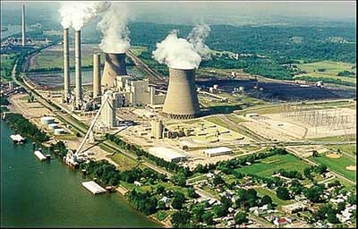
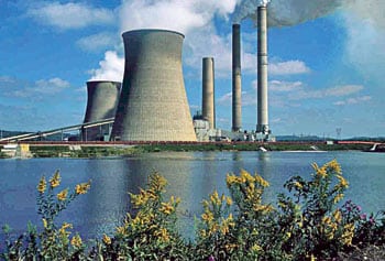
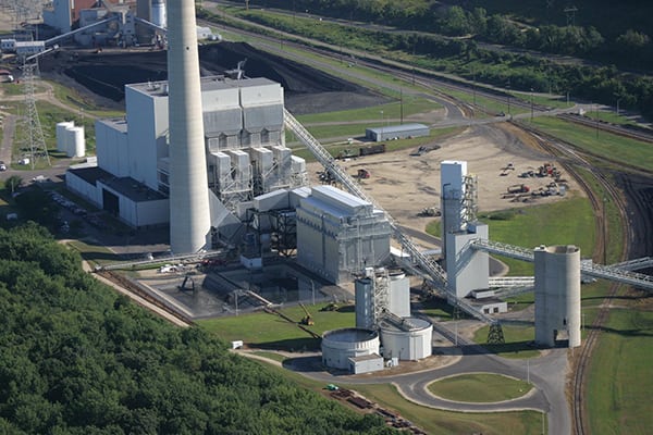
In order to maintain compliance with environmental law, coal-fired power generators have been required to retrofit their power plants with a variety of pollution control equipment, including baghouses, like the one at the Dairyland Power Cooperative’s John P. Madgett plant shown in the opening photo. A significant number of coal-fired generators adopted the use of selective catalytic reducers (SCRs) for the control of NOx emissions and wet flue gas desulfurization (wet FGD) for the control of SO2 emissions. Most recently, many have added the injection of dry sorbents or activated carbon for compliance with the Mercury and Air Toxics Standards (MATS). The rest of this article looks at the most common operation and maintenance (O&M) challenges posed by each of these pollution control systems.
SO2 Control
Fundamentally, wet FGD systems make use of an alkaline liquid or slurry (typically, lime or limestone slurry) to come in direct contact with combustion flue gas that is free from PM. Generally, the slurry solution resides at the bottom of an absorption tower and is circulated to a set of spray headers that disperse the slurry into fine droplets, contacting the flue gas in a counter-current manner. A variety of technologies exist to increase the gas-to-liquid contact area and enhance overall SO2 absorption. Spray towers, packed bed scrubbers, and venturi-rod scrubbers all have unique design features to optimize the gas-to-liquid surface area.
Due to the inherent nature of the scrubbing process, several operations problems exist among the various scrubbing technologies that cause additional maintenance activities or undesirable operating conditions. When flue gas passes through the absorber tower in the counter-current manner, liquid will become entrained in the gas stream and must be removed prior to discharge at the stack. To accomplish this on most wet FGD systems, a set of mist eliminators are installed to “dry” the flue gas of the entrained liquid.
Contained in the liquid droplets are various solids and dissolved species. When removed from the flue gas stream by the mist eliminators, the solids and dissolved species may leave deposits on the mist eliminators. These deposits may cause damage to the mist eliminators or result in material buildup and reduced mist removal efficiency. To overcome this operational headache of removing material buildup or replacing damaged mist eliminators, a wash system is typically installed to continuously clean the mist eliminators. The wash system also needs to be periodically inspected to verify valve functionality and proper spray distribution for adequate washing.
Reheater corrosion is another common maintenance problem experienced in wet FGD systems. Flue gas entering a wet FGD system is cooled by evaporation of water in the absorber tower. This cooling effect lowers the temperature of the flue gas close to the dew point of water. Left untreated, this cooled flue gas (downstream from the wet FGD process) increases the likelihood of moisture condensing on downstream equipment, resulting in corrosion problems. An additional concern is that the cooled flue gas may lead to poor gas dispersion from the stack and may result in higher-level concentrations of stack emissions.
For these reasons, a flue gas reheater is typically installed downstream from the mist eliminators. Wet FGDs using an inline heater (hot water or steam) are particularly susceptible to corrosion problems. Acid gases with dew points above the water dew point can condense on the finned surfaces of an inline heater. This acidic condensation will corrode the fins and tubes of a reheater system, resulting in replacement of tube sections or a whole reheater. Plants operating with high-chloride content in the flue gas are also susceptible to the development of chloride stress corrosion cracking of inline heaters (resulting in the same replacement requirements).
Replacing the existing materials with higher-grade materials (with better resistance to acid gas corrosion), such as nickel alloys, will significantly decrease this problem. Ensuring mist elimination systems are operating efficiently will also reduce inline reheater corrosion problems. Use of upgraded pH controls systems to more effectively monitor and correct chemistry imbalances within the wet FGD systems can also lead to better acid gas capture and less reheater corrosion.
Scale and sludge formation is an inherent maintenance problem with wet FGD systems. With the use of calcium-based reagents in a liquid solution, calcium deposits inevitably form on spray nozzles. Excessive scale formation typically occurs when the ratio between lime or limestone and water is increased. Proper operation of the wet FGD will minimize the amount of scale formation on the spray nozzles. However, periodic maintenance will still be required to remove scale buildup. Inspection and mapping of any plugged or highly scaled nozzles is recommended during scheduled maintenance.
Sludge handling is another inherent maintenance problem with wet FGD systems. The sludge that forms in a wet FGD system is a result of SO2 reacting with the lime or limestone to form either calcium sulfite or calcium sulfate. Typically, these reaction byproducts are allowed to settle out in the wet FGD and are collected in a liquid slurry or “sludge” form. If proper sludge removal procedures are not followed, the sludge can settle in discharge headers or at the bottom of the wet FGD and will harden over time. Eventually, this hardened sludge formation affects the operation of the wet FGD and will require time-consuming and expensive manual removal techniques.
NOx Control
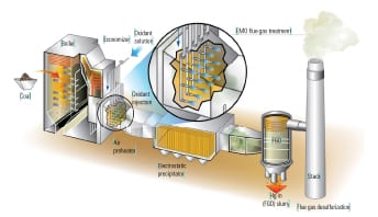
Although the maintenance aspects common to most wet FGD systems are somewhat unique, there are maintenance aspects for other systems and multipollutant control equipment that also must be considered. A common form of control for NOx to meet environmental regulations is the SCR (Figure 1). Heated flue gas is injected with ammonia and passes over a catalyst bed to reduce NOx to nitrogen and water. The SCR is typically located between the economizer outlet and air preheater inlet. Typical flue gas temperatures of between 600F and 700F yield maximum catalyst effectiveness while minimizing the potential for formation of ammonium bisulfate.
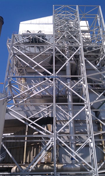 |
| 1. Retrofit consequences. Many SCR installations are designed and installed after the plant has started operations. This leads to longer duct runs with multiple direction changes and a greater potential for ash accumulation problems. Courtesy: Brandon Bell |
One of the more common maintenance headaches associated with SCR operation is ash pluggage within either the catalyst bed or downstream air preheater. The reason for the greater degree of concern of ash pluggage within an SCR, but not a wet FGD, is that the SCR is typically located upstream of particulate control devices while the wet FGD is downstream of these devices. Various types of ash plugging may occur, and proper ash control strategies can avoid the need for a forced outage.
Fly ash is a fine particulate that results from the combustion of coal and is light enough to become entrained in the flue gas stream. At various points in the boiler there are collection hoppers for fly ash; however, a large portion of fly ash will remain entrained in the flue gas until removed by a particulate control device (such as a fabric filter or ESP). An SCR is not designed to handle storage or removal of ash, which is why it is problematic when ash buildup occurs. Horizontal surfaces in the SCR can initiate the buildup of ash, which then propagates to other parts of the reactor, causing the catalyst to plug. Sonic horns and sootblowing help remove this buildup, but changing the geometry of these horizontal surfaces (to an inclined surface) will promote improved shedding capabilities and lessen ash buildup.
“Popcorn” ash has become another significant maintenance headache that plugs SCRs and may require manual removal techniques. Popcorn ash is a light and porous material and can reach upwards of 1 inch in size. Because popcorn ash is larger in size, does not break apart easily, and has a tendency to interlock with other particles, conventional fly ash removal techniques have been ineffective at removing buildups of it. Eventually, the popcorn ash builds up on the top layer of SCR catalyst, reducing gas flow paths, and contributes to an increasing pressure drop that forces the operator to prematurely bypass or shut down the SCR to clear the popcorn ash.
Due to the low sulfur content typical of most Powder River Basin (PRB) coals, many plants are switching to this fuel source to help lower their SO2 emissions. However, PRB fuels also tend to have a higher propensity for popcorn ash formation. In order to avoid costly shutdowns, de-rating of units, or noncompliance with environmental regulations, alternative strategies to avoid popcorn ash buildups need to be implemented. There are two relatively simple ways to mitigate this problem: one uses aerodynamics and the other is a simple screen.
Computational fluid dynamic (CFD) modeling can be used to model ash flow from the economizer outlet to the SCR and the capture rate of the economizer ash hopper. Typically, the geometry of an economizer hopper allows for popcorn ash to accumulate and then become re-entrained in the flue gas stream. In some instances, CFD modeling will reveal that the addition of a baffle plate at the exit of the economizer outlet can change the trajectory of the fluidized popcorn ash and direct it back into the economizer hoppers.
In some cases however, modifying the aerodynamics of the flue gas steam is ineffective, and a screen is needed to prevent popcorn ash from migrating to the SCR. The screen should be designed with openings that are smaller than the openings for the catalyst. This design will capture larger popcorn ash that would otherwise plug the catalyst. The screen should also be installed with a forward incline over the economizer hopper. With the forward incline, popcorn ash captured by the screen has a greater chance of falling into the economizer hoppers.
Plugging of catalysts beds by ash is not the only concern when operating an SCR. With baseload coal plants cycling more frequently and operating at lower loads, ammonia bisulfite formation becomes a larger concern. Ammonia bisulfite formations occur when ammonia reacts with sulfur trioxide (SO3) and water to form ammonia bisulfite. This formation is problematic, as it will condense on equipment at temperatures much higher than acid dew point temperatures. When ammonia bisulfite condenses, it forms a sticky liquid that binds with fly ash and plugs small passages. The air preheater (typically located downstream of the SCR) will experience the greatest impact, as flue gas temperatures are reduced in this equipment and many small passages exist in the air preheater baskets. With ammonia bisulfite present in the flue gas stream, air preheater plugging and unit de-rating or forced outages are probable.
Higher amounts of unreacted ammonia occur when there are lower temperatures entering the SCR reactor, leaving the catalyst less effective at reacting ammonia with NOx. Unfortunately, operating in a low-load scenario increases the probability of low flue gas temperatures entering the SCR reactor.
Consistent cycling of a plant increases the probability of ammonia injection operating during the startup or shutdown cycles, when reduced flue gas temperatures are also observed in the SCR reactor. Both of these scenarios increase the likelihood of ammonia bisulfite forming and plugging the air preheater. To avoid this costly maintenance issue, better controls to limit the amount of ammonia being injected into the SCR reactor can prevent ammonia bisulfite formation. Heating of the flue gas to proper reaction temperatures using steam will increase the effectiveness of NOx reduction and reduce the formation of ammonia bisulfite.
Mercury and Air Toxics Control
More recently, additional pollution control equipment has been installed at many power plants to meet the Mercury and Air Toxics Standards. A common approach to complying with MATS is the addition of a dry sorbent injection system (Figure 2). (See “The State of U.S. Mercury Control in Response to MATS” in this issue.) These systems will use either a calcium- or sodium-based sorbent to neutralize acid gas emissions. For maximum effectiveness, the sodium-based sorbents are typically injected upstream of the air preheater, while calcium based sorbents, such as hydrated lime, will be injected downstream of the air preheater.
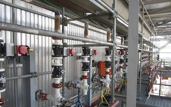 |
| 2. Latest addition. Dry sorbent injection piping is being installed at the outlet of an SCR. Courtesy: Brandon Bell |
The injection of these sorbents (primarily around the air preheater) will affect the performance of downstream particulate control devices. For plants operating with an ESP, the injection of sorbents will change the ash resistivity characteristics and thus affect the removal efficiency of the particulate. For plants that use either an ESP or a baghouse for particulate removal, increased particulate loading will be an adverse side effect of sorbent injection systems.
For an ESP, even if the change in ash resistivity is favorable, increased particulate loading from sorbent injection systems will affect ESP outlet emissions. For both baghouses and ESPs, fly ash removal systems will be affected. The existing fly ash–handling system will need to be evaluated to determine if adequate removal rates are achievable.
Mercury control is also typically achieved by use of an activated carbon injection system. Similar to sorbent, powdered activated carbon (PAC) is injected either upstream or downstream of the air preheater. The use of PAC may slightly reduce the resistivity of the fly ash, thus affecting the performance of an ESP. A more substantial impact to consider when using PAC is the salability of fly ash for secondary use. Depending on the quantity of PAC injected to comply with environmental regulations, the PAC may increase the carbon content of the fly ash to a point where it may no longer have a secondary use and must be sent to a landfill.
Counter Complexity with Careful Attention
Proper operation of pollution control equipment can be challenging due to deficiencies in equipment design, changes in fuel composition, or operating in load scenarios not originally anticipated. However, proper maintenance practices and diligent oversight of plant operations will reduce forced outages and decrease equipment damage. Utilities will continue to push the boundaries of pollution control, and further impacts can be expected in the future. ■
— Brandon Bell, PE (bbell@valdeseng.com) is senior project manager for Valdes Engineering Co. and a POWER contributing editor.