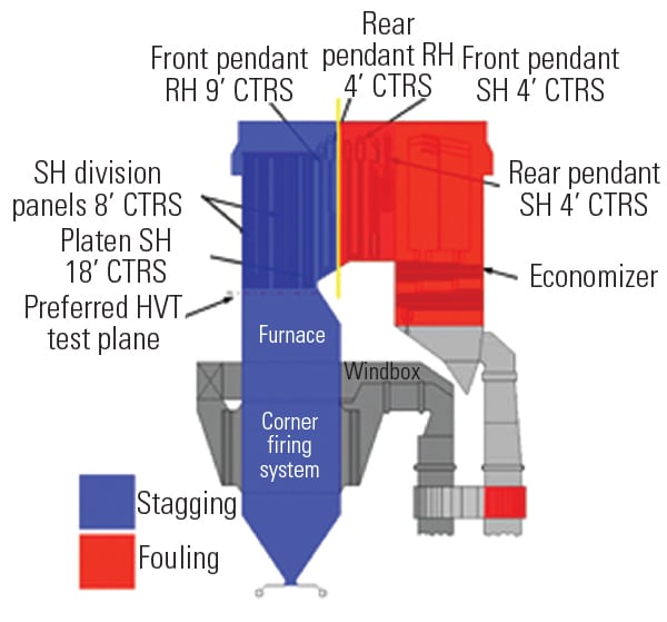
All coals contain mineral matter in their ash. Slag deposits form when molten or sticky particles of flyash are quenched upon contact with furnace walls or other radiant surfaces. The deposits reduce heat transfer to the walls and increase the amount of heat in the boiler’s convective pass. The resulting rise in furnace exit gas temperature (FEGT) increases the temperatures of main and reheat steam, desuperheating spray flows, and NOx emissions. For best boiler performance it is important to maintain an optimal balance between furnace and convective pass heat transfer.
Sootblowing with high-pressure steam or air is the method of choice for keeping boiler heat-transfer sections free of slag. Wall blowers and water cannons are used to remove slag from the furnace’s water walls, while retractable blowers are used to clean the boiler’s convective pass, including the air preheater. Furnace sootblowing restores heat transfer in that area, reducing FEGT, steam temperatures, desuperheating sprays, and NOx emissions. Convective pass cleaning increases steam temperatures and desuperheating sprays and reduces boiler exit gas temperature.
The challenge in sootblowing optimization is to determine which sections of the boiler to clean and how often. Economic tradeoffs among NOx output, the opacity of stack emissions, steam temperatures, efficiency, boiler tube life, sootblower steam consumption, and O&M costs must be considered.
Getting sootblowing frequency and location just right can yield substantial economic benefits. For a typical 600-MW unit, optimal sootblowing can lower heat rate by 20 Btu/kWh and NOx emissions by 0.020 lb/mmBtu. Assuming a fuel cost of $1.50/mmBtu, NOx credits priced at $2,000/ton, and a five-month ozone season, those two reductions alone can lower a boiler’s annual operating costs by approximately $500,000. Accounting for avoided power generation losses increases financial benefits by a factor of ten or more.
Knowledge is power
Lehigh University’s Energy Research Center (ERC) has developed a unique, knowledge-based expert system (KBES) for sootblowing optimization based on the premise that knowledge is stronger than data. The KBES is implemented as a computer code called IntelliClean. At the heart of the program is a robust database that characterizes the effects of sootblowing using parameters such as the cleanliness of heat-transfer surfaces, steam temperatures, attemperation spray flow, emissions level, and stack opacity.
Powered by KBES, IntelliClean uses live process data (process events) to make real-time, on-line decisions about optimal sootblower activation. The optimal sootblowing activation strategy is event-driven and selects sootblower groups to be activated when and where needed to satisfy the sootblowing optimization goal and imposed operating and environmental constraints.
The characterization data are obtained by activating sootblowers or groups of sootblowers one at a time and recording and analyzing the effects. This data, and boiler operating data, then are integrated in a knowledge base that is used by KBES and IntelliClean to develop an optimal sootblower activation strategy. Significantly, the strategy is site-specific because the data in the knowledge base are empirical, representing the results of using sootblowers installed at particular locations on a particular boiler with a unique internal configuration.
Maiden voyage
Field trials of the ERC sootblowing optimization approach were the next order of business. The ERC teamed up with Natural Resources Canada (www.nrcan.gc.ca)—a federal department also known as CANMET—to install the Sootblowing Advisory System (SAS), consisting of IntelliClean and an Ash Monitoring System (AMS), on Unit 3 of Ontario Power Generation’s Lambton Generating Station. Unit 3, rated at 520 MW, is powered by a subcritical, divided-furnace, tangentially fired boiler that burns medium-sulfur eastern bituminous coal. The furnace is cleaned by 54 wall blowers at three elevations, while 18 retractable blowers at seven elevations clean the heat-transfer surfaces in the boiler’s convective pass (Figure 1).
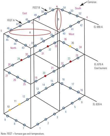
1. Off the wall(s). The sootblower arrangement within Lambton Unit 3’s furnace. Source: Lehigh University Energy Research Center
Before the SAS was deployed, Unit 3’s operators lacked any first-hand indication of the boiler’s internal cleanliness. Relying on their experience, they activated a preprogrammed sootblowing sequence whenever they believed slagging was reducing heat transfer. Lambton’s staff realized that optimizing sootblowing operation would reduce erosion damage to boiler tubes, enable more precise control of steam temperatures, and improve Unit 3’s bottom line.
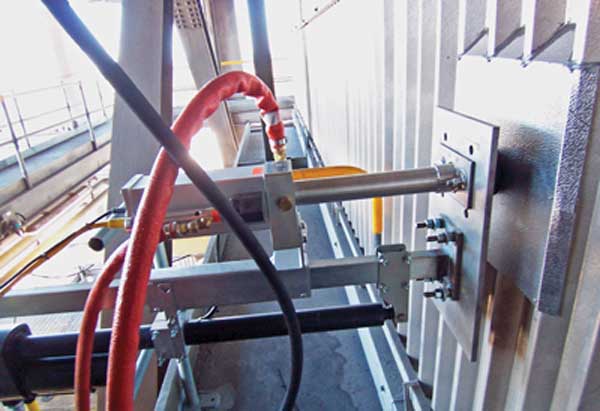
The AMS used a series of heat- and mass-balance calculations to convert process measurements into information on cleanliness factors for the boiler’s convective pass sections. The cleanliness of the lower furnace was inferred from readings of another proxy variable: FEGT. The FEGT measurements came from a pair of infrared gas temperature probes installed at the exit of the lower furnace.
Using the cleanliness factors provided by AMS and process data, ERC engineers conducted characterization tests of Unit 3’s sootblowers under full-load operating conditions. Subsequent analysis of the data correlated the effect of activating individual sootblower groups on the cleanliness of convective-pass sections and on boiler performance and emissions. The correlations became the basis of an advisory-mode version of IntelliClean tailored for Unit 3 that was made available to operators in December 2005.
As part of the deployment, engineers developed new screens for displaying the SAS results using the plant’s distributed control system. The overview screen (Figure 2) shows the process data, cleanliness status, and the time elapsed since the last sootblowing event for all boiler heat-transfer sections. Separate "detail" screens for each boiler heat-transfer section graphically correlate its cleanliness with local sootblower operation. The SAS sootblower activation strategy (Figure 3) is radically different from the regularly used fixed sootblowing schedule.
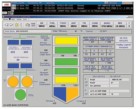
2. Screen test. The overview screen of the Sootblowing Advisory System. Courtesy: Lehigh University Energy Research Center
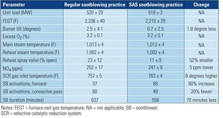
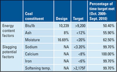
Table 1. Results of testing the Sootblowing Advisory System at Lambton Generating Station. Source: Lehigh University Energy Research Center
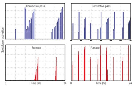
3. More for less. A comparison of fixed-time (L) and event-driven (R) sootblowing activation strategies for convective-pass and furnace surfaces. Source: Lehigh University Energy Research Center
4. Keeping your cool. Average reheat steam temperature spray valve position for the Sootblowing Advisory System vs. regular sootblowing practice. Lower spray flow implies lower heat rate. Source: Lehigh University Energy Research Center
Daily variations in burner tilt angle and attemperator spray valve positions also were smaller, compared with fixed-time sootblower activation. The last three rows of Table 1 illustrate that, despite increasing the furnace sootblowing frequency, the SAS strategy decreased total sootblower running time by 70 minutes or 11%, reducing erosion (furnace wall blowers run for 1 minute, whereas those in the convection pass run for 10 minutes).
Also, due to the lower burner tilts, NOx emissions were lower, reducing the total ammonia flow to the unit’s selective catalytic reduction (SCR) system. Steam temperature setpoints were preserved by both sootblowing strategies. The average SCR gas inlet temperature with the SAS in operation was 763F, about 5 degrees higher than that of traditional sootblowing at Lambton. The reason for this slightly higher temperature: The SAS maintained the SCR gas inlet temperature below the default setpoint value of 770F.
Another success
The second test of the SAS was conducted at PSE&G’s Bridgeport Harbor Generating Station’s 400-MW Unit 3, located on Long Island Sound in Connecticut. Its tangentially fired boiler was converted to burn a blend of Eastern coals and low-sulfur Indonesian coals. Indonesian coals are characterized by a low heating value, high moisture content, and a low ash-softening temperature that together foster slagging of a steam generator’s upper furnace and division walls. Although slagging in Unit 3’s lower furnace is light, due to slag’s high reflectivity, furnace wall blowers have to be activated frequently to keep FEGT below 2,500F.
The objective of the testing at Bridgeport was to develop a sootblower activation strategy optimized to maintain unit performance and eliminate opacity-caused load runbacks. Unit 3’s stack opacity is prone to spiking at high loads and high ambient temperatures due to large temperature stratifications at the inlet of the unit’s marginally sized electrostatic precipitator (ESP). When opacity exceeds 20% for longer than the prescribed period, Unit 3 must be derated.
Unit 3’s furnace is cleaned by 48 wall blowers at three elevations; slag in the boiler’s convection is removed by 18 retractable blowers arranged as two groups of nine units (Figure 5). One infrared probe at the furnace exit plane measures FEGT.
5. All over the map. Sootblower locations at Bridgeport Station Unit 3. Source: Lehigh University Energy Research Center
A fixed sootblowing schedule programmed into the sootblower control system is available to Unit 3’s operators for use at their discretion. Historical operating data indicated that sequential activation of all 48 wall blowers produced large cyclic variations in main steam temperature. The main steam temperature rose as the convection pass was cleaned and fell as slag was scoured from the furnace water walls. Such cycling of main steam temperatures is not desirable because it stresses both the boiler and the steam turbine.
The first orders of business were once again characterizing the effect of sootblowing and developing the system’s knowledge base. The IntelliClean algorithm was implemented at Bridgeport and entered service in on-line advisory mode in August 2005. In the spring of 2006 plant controls engineers put IntelliClean in closed-loop control mode. Since then, IntelliClean has controlled Unit 3 sootblowers on a 24/7 basis.
Field testing was performed in late August 2006. Data collected during the tests showed that with the normal sootblowing sequence, multiple load runbacks—caused by high and lingering opacity spikes—occurred during a typical day (Figure 6). With IntelliClean in service, opacity spikes were less frequent, smaller in magnitude, and shorter in duration (compared with the regular sootblowing sequence), and load runbacks were eliminated. The results (Table 2) also show that IntelliClean was successfully controlling FEGT and main and reheat steam temperatures close to their setpoints of 2,450F, 1,005F, and 1,005F, respectively.
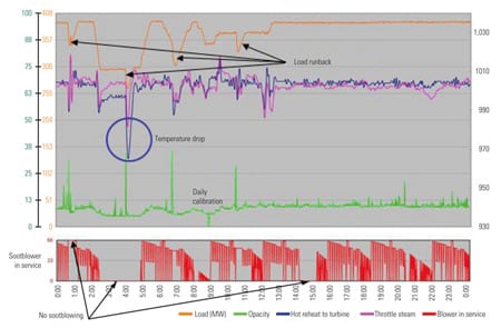
6. Rough seas. Opacity spikes (green) and opacity-induced load derates (orange) under regular fixed-time sootblowing practice. Source: Lehigh University Energy Research Center
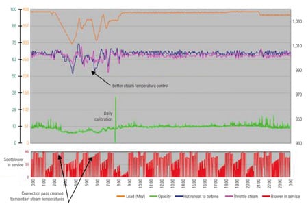
7. Clear sailing. With IntelliClean running in closed-loop control, opacity spikes and opacity-induced load derates were eliminated. Source: Lehigh University Energy Research Center
The author wishes to acknowledge the contributions of Dr. Carlos Romero, Dr. Xiaodong Bian, and Ph.D. candidate Wei Zhang of ERC; Bruce Clements and Richard Pomalis, CANMET; Chris Micu and Collin Andrews, Lambton Generating Station; and Michael Cilinski, Thomas Johnson, and John Bokowski, Bridgeport Harbor Generating Station.
—Dr. Nenad Sarunac is a principal research engineer and associate director of the Energy Research Center at Lehigh University. He can be reached at 610-758-5780 or ns01@lehigh.edu.