Eskom operates 23 power stations in South Africa with a total capacity of more than 42 GW. It supplies about 95% of all the electricity used in the country. One of its coal-fired power stations was experiencing frequent boiler tube fatigue failures in the hopper section—the bottom part of the boiler—of all six units.
The boilers were designed with a complex support beam structure that cradles and surrounds the boiler. Pivoting attachment mechanisms exist between the support beam structure, or buckstays, and the tube wall to allow for thermal expansion while still providing adequate support on all four sides.
The boiler can expand up to a meter downwards during a startup sequence. Buckstays join at corner junction locations of the hopper where the slope walls and front/rear walls join. They are connected to each other using hinged members referred to as buckstay connection links.
These junctions necessitate the rerouting of the surrounding front/rear wall tubes, leading to discontinuities in tube layout. High tube failure rates were identified at these tube manipulations and the areas were considered to be possible high-stress locations.
Modeling Boiler Stress
A suspected cause of the repeated tube failures (Figure 1) was that cyclic operation of the plant to accommodate increased intermittent renewable energy resources and reduced electricity demand during off-peak hours was causing cyclic fatigue in the tube material. Because the plant was designed for consistent operation at full load, the cyclic fatigue was leading to component damage and reliability problems. The failures resulted in unscheduled shutdowns, emergency repairs, and unexpected costs.
 |
|
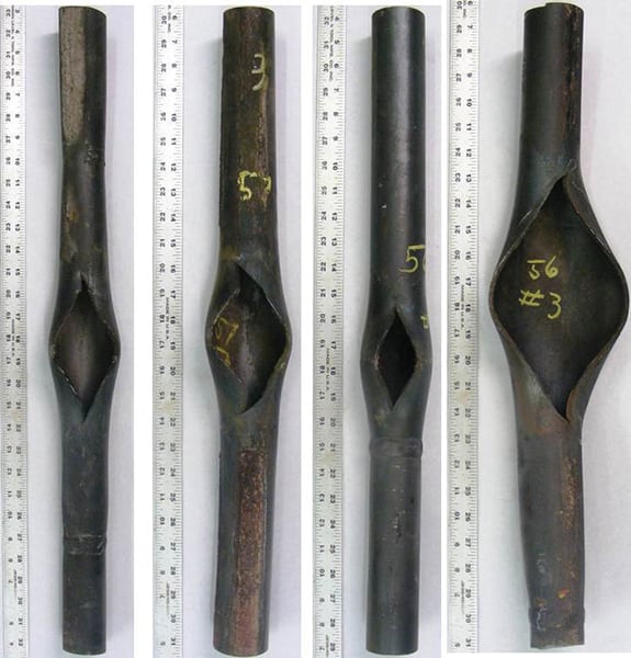
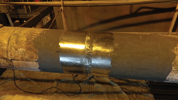
1. Fatigue failure. This image shows a typical boiler tube failure location at the Eskom-owned plant. Courtesy: Flownex SE |
It was also believed that the delayed effect of cooling water being supplied between two adjacent boiler tubes of different tube banks could be a contributing factor to thermal fatigue failure. The argument presumed that a column of water from the economizer outlet would reach the closest tube bank first, the second bank next, and so forth. It was alleged that this would cause a significant fluid temperature differential between the first bank’s outermost tube and the adjacent tube of the second bank.
To test the hypotheses, a unique one-way fluid structure interaction (FSI) methodology was developed to model and predict the induced fatigue loading during a boiler startup cycle. Fluid flow and heat transfer was transiently modeled using a 1-D pipe flow modeling tool supplied by Flownex Simulation Environment and validated against experimental data. The 1-D flow solver was a thermo-fluid simulations software package used to predict, design, and optimize flow rates, temperatures, and heat transfer in fluid systems. The one-way FSI modeling approach allowed a transient thermal load, or any user-selected transient step, to be coupled with a 3-D finite element analysis (FEA) software supplied by ANSYS to evaluate the thermal-induced stress.
Validation Offers Assurance
Half of the four boiler hopper walls were modeled to obtain a representative sample of the complete hopper section. Instrumentation, including thermocouples and strain gauges, was also installed in the modeled area of the hopper section to obtain measured plant data. The Flownex model consisted of 1,219 tubes and 1,858 vertices/nodes.
Flownex’s capability to fundamentally calculate flow and heat transfer behavior of both fluid and tube wall material during steady state and dynamic conditions was considered an ideal fit for the testing. Using the same economizer outlet temperature profile as obtained during the plant measurement sequence, together with adjusted gas-side heat transfer properties, a dynamic startup scenario was modeled to validate the results from the model against that of the measured plant data. A number of other scenarios were also successfully modeled.
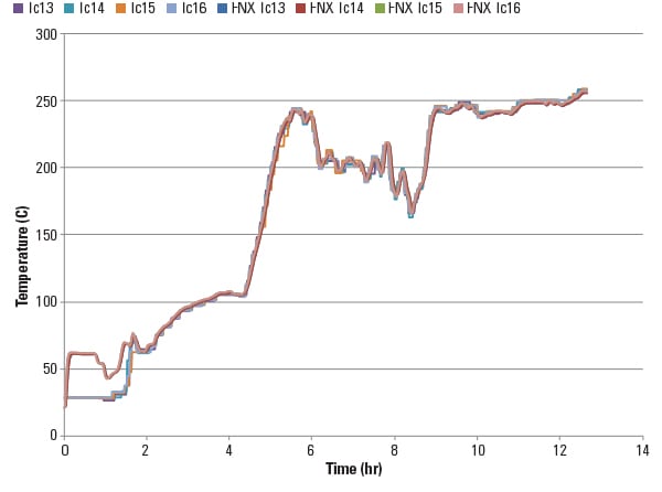
The results obtained from the model corresponded very well with the measured plant data (Figure 2). The strong correlation enabled the model to be used for various postulated plant conditions and operating sequences. The temperature distribution results from Flownex were then imported into ANSYS, where the structural stress analysis was performed (Figure 3).
 |
|
2. Flownex model validation. The 1-D solver results (denoted as FNX Tc13 through FNX Tc16) correlated very closely with the data from installed thermocouples (denoted as Tc13 through Tc16). Courtesy: Flownex SE |
 |
|
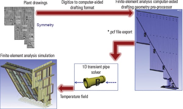
3. Mapping procedure. A 1-D line geometry created in a computer-aided drafting package was imported into Flownex simulation software to obtain thermal results, which were exported to ANSYS software for stress analysis. Courtesy: Flownex SE |
The methodology allowed the examination of various scenarios to evaluate causes of failures without affecting plant operations. It also facilitated the modeling of the massive boiler structure, which could not have been done economically using 3-D computational fluid dynamics simulations.
Simulation Leads to Answers
The results from the developed model indicated that the delay in water supply between the first tube bank’s outermost tube and the adjacent tube of the second bank did not induce perturbing stresses as postulated. The maximum temperature differential was calculated to be only 2.2C. This proved to be due to the conduction and thermal inertia of the tube walls and webbing, which resulted in a smooth transition in adjacent tube wall temperatures.
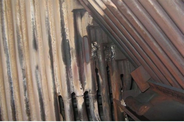
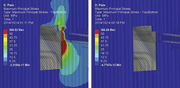
Having ruled extreme temperature differentials out, the effects of structural support members in the form of welded support plates at the buckstay junction locations were evaluated. The developed methodology facilitated comparisons between two cases considered: first, where the buckstay sliding joint plates were present, and second, a case where these plates were removed (Figure 4). In evaluating these scenarios, the model clearly showed that stress worsened in the presence of the plates.
 |
|
4. Stressed out. Contour plots colored by maximum principal stress at the buckstay junction location are shown here for both cases where the sliding joint plate is present (left) and removed (right). Courtesy: Flownex SE |
With this new knowledge, Eskom was able to make modifications to the boiler structure to reduce induced stress. Plates were removed, which greatly reduced tube wall stress without compromising the integrity of the surrounding structure.
Initial data taken following the modification indicated that strain at the locations previously susceptible to damage had been reduced. Strain data collected over a two-year period prior to solution implementation was compared to data collected after the changes. From the time-averaged data, it was shown that average strain and subsequent stress-induced fatigue loads have been reduced by approximately 50%.
A Valuable Tool
The ability to eliminate, through simulation, non-contributors to failure and identify potential new failure mechanisms has proven to be a powerful engineering tool. The developed one-way FSI methodology has been demonstrated to be effective in solving problems of thermal-induced stress fatigue loading as a result of fluid-coupled thermal flow. Obtaining a thermal field from 3-D computational fluid dynamics, as used for structural FEA boundary conditions, is not practical due to the size of the problems considered. 1-D to 3-D one-way FSI coupling is not only a feasible alternative, but it also is an effective and efficient solution.
Similar problems have been reported at various other Eskom power stations. Identifying the main contributing factor to these stresses may lead to the mitigation of numerous outages due to tube failure repairs, which in turn will result in a significant financial benefit to Eskom and improved reliability for customers. ■
—Marius Botha and Michael P. Hindley were members of Eskom’s Research Testing and Development team tasked with solving the plant’s tube failure problem.