Creeped out and fatigued—that’s the state of many coal-fired boilers these days. Understanding failure mechanisms and suitable testing methods for identifying potential trouble can help you find problems before the problems find you.
Even as the current regulatory environment pushes new power generation to utilize natural gas over other fuel sources, a significant amount of existing coal-fired generation remains in operation. A majority of these coal-fired power plants have been in existence for a long time—the average age is near 40 years. Keeping these plants online and running efficiently presents a challenge, but with programs in place to effectively monitor equipment condition and replace critical parts at optimal times, these units can continue reliable operation for years to come.
Modes of Failure
For long-term operation of coal-fired steam generators, creep and thermal fatigue are the two damage mechanisms that typically affect boiler integrity. Boilers can also be damaged by chemical imbalances in water or flue gas chemistry, but generally those problems can be corrected in a short period of time.
Thermal Fatigue. Thermal fatigue is experienced from cyclic stresses caused by temperature gradients that vary over time. Steam generators experience the greatest amount of thermal fatigue during startup and shutdown activities.
In high-temperature boiler tubes, localized high-stress areas will plastically deform until the stress is relieved. This deformation process, while providing temporary relief to components at elevated temperatures, also introduces new stresses in these same components as the system cools—with material unable to return to its original position.
Boiler designers anticipate a planned number of startup and shutdown cycles and design the boiler to handle these scenarios. However, excessive cycling of a steam generator, either as a result of being dispatched too frequently or being brought down in unplanned, forced outages (due to poor equipment reliability) will prematurely push the boiler past its original design life. The excessive cycling will ultimately lead to thermal fatigue cracking of boiler tube elements. Typically, thermal fatigue occurs at weldments or points of configurational change.
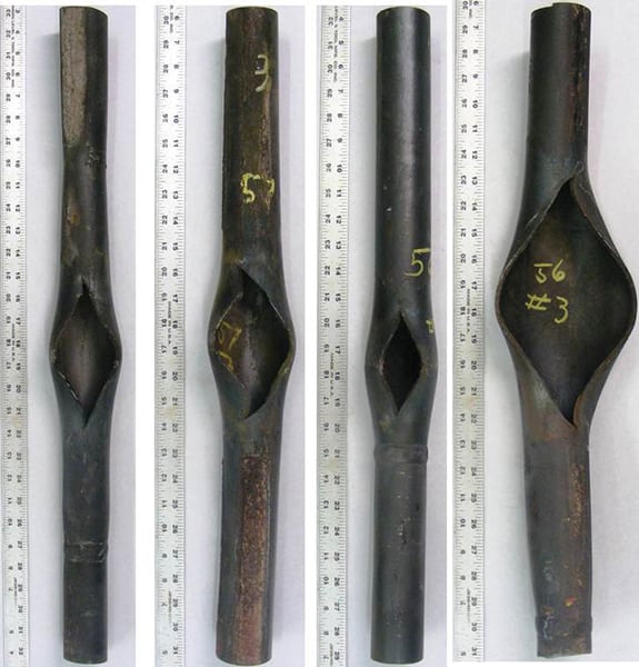
Creep. The second significant mechanism of steam generator tube failures is creep. Creep is a progressive, permanent deformation of a material under stress at high temperatures.
When materials are manufactured, microvoids form within the material structure. Over time these microvoids begin to propagate and interconnect, forming cracks within the material. The deformation occurs plastically and causes a thinning of the material, which results in higher stresses and an increasing creep rate. This phenomenon can occur in materials experiencing high stresses, but still at levels below the yield strength of the material.
Creep occurs in three defined stages during the life of a material. The first stage is commonly referred to as primary creep. During this stage the strain rate is high, but it rapidly slows with time as a result of work hardening. This first stage of creep is relatively short-lived and results in no significant changes to the material structure.
The next phase of creep is the secondary, or steady state, phase. The material will experience secondary creep for the majority of its lifespan. This stage is defined by a relatively constant strain rate, where work hardening is balanced by its recovery rate.
The final stage of creep, the tertiary phase, is defined by rapid elongation over time. This rapid elongation will accelerate until failure of the material occurs.
Predicting Lifespan
There are mathematical approaches to calculating the useful life of a material versus time and temperature. General Electric engineers developed one method in the 1950s that can be used to extrapolate experimental data for creep and rupture strength of materials. It’s known as the Larson-Miller Parameter and is expressed as:
P = T x (C + log t) x 10-3
where:
T is the absolute temperature of the material during operation
t is the number of hours in service
C is a constant (typically a value of 20), and
P is the Larson-Miller Parameter
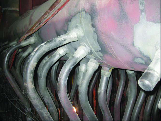
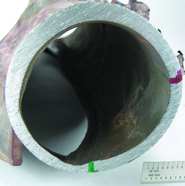
Thermal fatigue cracking tends to be a localized phenomenon that can be identified using conventional nondestructive examination methods. Once thermal fatigue cracking is identified, welding can easily repair it. Creep damage typically is identified using metallographic examination methods. If a material has been identified to be in the tertiary stage of creep, simple repairs are not possible, and replacement of the material is required (Figures 1 and 2).
|
| 1. Out with the old. This main steam header developed ligament cracks from many years of operation and thermal cycling. It had reached its end of service life and required replacement. Courtesy: Brandon Bell, PE |

|
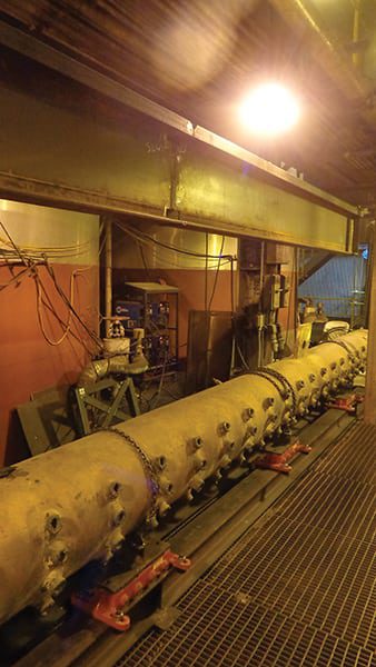
| 2. In with the new. Installing this replacement steam header will extend the plant’s operation for years to come. Courtesy: Brandon Bell, PE |
Analyzing Boiler Materials
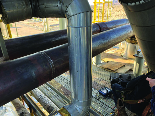
To avoid forced outages resulting from thermal fatigue and creep, nondestructive examination techniques can be used to determine the state of materials (Figure 3). When used effectively, these techniques are able to track the progression of either thermal fatigue or creep, which helps plants plan in advance for replacement of components rather than waiting for material failure and then scrambling to correct the problem. Some commonly used nondestructive examination techniques follow.

|
| 3. Visible defects. No special nondestructive examination techniques were needed here. A simple visual inspection revealed that several pressure part supports were either damaged or missing and needed repair. Courtesy: Brandon Bell, PE |
Liquid Penetration. A common nondestructive examination technique used for detecting surface cracking on a material is called liquid penetration. This technique is very versatile, as it does not require specific material properties for the metal being tested.
Prior to the material being tested, it must be cleaned of any contaminants and allowed to dry. A low-tension liquid with a visible dye is then applied to the surface of the material, at which point the capillary effect will draw the liquid into any discontinuities in the metal. Any excess liquid is removed from the surface prior to inspection.
Under a white or fluorescent light, the material is inspected for the presence of the liquid penetrant. The presence of the liquid penetrant indicates voids in the surface material, either from cracking or porosity of welds.
Ultrasonic Testing. Ultrasonic testing (UT) is a powerful tool that is used to detect and evaluate flaws in a material and characterize the material flaws. It also can be used to measure thicknesses of materials. UT testers make use of three basic components: a pulser-receiver, a transducer, and a display device.
This technology generates a high-frequency ultrasonic wave that is transmitted through the material being tested. When the sound wave is generated at the surface of the material using the pulser, it quickly propagates through the material structure at a known velocity. If the sound wave encounters a discontinuity in the grain structure of the material, a portion of the initial sound wave is reflected back to the receiver. The sound wave will continue until it reaches the opposing boundary of the material and the remaining sound energy is reflected back to the receiver.
The receiver captures the intensity and intervals at which the initial sound wave is reflected. This data can be processed into a graphical result on the display device. Readings are displayed in real time—providing the user with instantaneous results. With the sound wave processed, a technician or engineer can evaluate any flaws found in the material structure while assessing overall material thickness throughout.
Determining the thickness of the material in service is critical to calculating the material’s ability to resist stress. The minimum wall thickness for a material can be calculated using a variety of material properties and operating conditions. The calculation uses the following relationship:
tm = PD / 2 x ( SE + Py) + A
where:
tm is the minimum wall thickness
P is the internal design pressure
D is the outside diameter of the pipe
SE is the maximum allowable stress of the material at the design temperature
y is a coefficient (based upon material properties and design temperature), and
A is any additional thickness (for example, an allowance for corrosion/erosion)
Comparing the actual wall thickness to the minimum wall thickness will identify if the element needs to be replaced as a result of loss of material.
Phased Array Ultrasonic Testing. An offshoot of standard UT testing is the phased array ultrasonic testing (PAUT) method. Also a nondestructive examination technique, the PAUT method makes use of multiple probes that emit high-frequency ultrasonic waves.
The introduction of the sound wave is time-delayed from element to element in order to produce a focal point to be analyzed. The timing of the sound waves can be varied in order to “sweep” the material and scan for imperfections. As with UT, the results are viewed in real time, allowing the user to locate and identify material flaws instantaneously.
Magnetic Particle Testing. Magnetic particle testing (MT) is a nondestructive examination method used to identify linear flaws at or near the surface of a material. With the MT technique, the material being tested is magnetized, which produces flux lines along the surface of the material.
Flaws or discontinuities in the material distort the flux lines, causing the magnetism to leak out. Dissipation of the flux lines creates regions of magnetic polarity. When magnetic particles are applied to the surface of the material, they visibly pool together in these areas of high polarity and highlight areas with flaws or discontinuities.
Alternately, this test can be performed by using wet magnetic particles mixed with fluorescent dyes, similar to that of liquid penetration inspections. Compared to dry particles, the use of wet particles provides for a more effective media to fill into cracks and fissures found in the material. When viewed under a black light, the use of a fluorescent dye will clearly highlight material cracking to the inspector.
The MT technique is quick, simple, and yields real-time results for cracking as a result of creep. However, the test method is limited only to materials that are ferromagnetic. After completion of the test, the material will need to be demagnetized, typically using an alternating current coil.
Replication Metallography. In order to view the grain structure of a material at high magnification, a nondestructive examination technique called replication metallography can be used. It provides a mirrored image of a material’s structure.
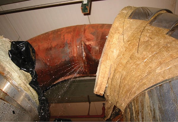
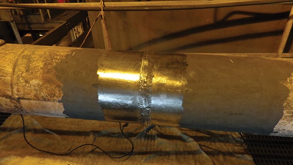
In order to provide this level of detail, the material to be tested needs to be cleared of any contaminants and polished to a smooth mirror-like finish. This can be a time-consuming and laborious process, as manual techniques are typically required to clear scale and rust from the installed material (Figure 4).
|
| 4. Clean as a whistle. This pipe’s surface has been cleaned thoroughly for inspection of a critical weld. Courtesy: Brandon Bell, PE |
After the material has been cleaned and polished, a chemical etchant is applied to the surface that allows the grain structure to be revealed. The chemical used, and duration of application (to reveal the material’s grain structure), will be chosen based on the material being tested.
A replicating material will then be applied to the material surface to embed the grain structure into the replicating material. Once the material dries, it can be removed and sent for microscopic observation. The replicating material will now reveal the grain structure of the material without compromising the integrity of the material itself. The process will give insight into only the grain structure at the surface of the material and is used on base metals and critical welds alike.
High-Energy Pipe Surveillance
In addition to employing nondestructive examination techniques, conducting surveys of a plant’s high-energy piping systems should be a routine occurrence. High-energy piping systems typically include main steam, hot reheat, cold reheat, boiler feedwater, and turbine extraction piping systems. High-energy piping surveys analyze stress and strain on the piping and support system. This is critical for extended plant operation, because the survey can detail areas of concern that can be corrected prior to a material or pipe support failure.
As these high-energy systems operate over time, hanger adjustments are sometimes made that change the dynamics of the system. Additionally, poor initial designs, changes in modes of operation, or plant preferences can result in the addition or removal of key pipe support elements. Because high-energy piping expands and contracts considerably during startup and shutdown cycles, if such changes are not properly implemented, the system will grow, bend, or cycle in an undesirable way.
In order to effectively evaluate these high-energy systems, they need to be observed in the two extreme states of operation. Documenting the hanger positions in both hot (full-load operation) and cold (zero-load cold plant) conditions allows engineers to model the stress and strain of the system. This modeling can then be compared against the original design and evaluated for proper support and growth allowance. The results will dictate if adjustments to hangers are required or if new support hardware is necessary to bring the system back into allowable stress ranges.
Although it may be challenging to continually inspect and document the material condition of steam-generating equipment and high-energy piping, the payback will come in the form of increased equipment reliability and availability. Shutdowns as a result of forced outages are costly, due to the likelihood of expedited material purchases and uncertain availability of skilled craft labor. Establishing programs to track and plan for repairs will lead to fewer forced outages and longer plant life. ■
—Brandon Bell, PE (bbell@valdeseng.com) is lead project manager for power projects at Valdes Engineering Co.