A common concern for gas turbine power plants is treating exhaust gases to comply with laws restricting pollutants present in the gases that are emitted into the ambient atmosphere. The challenge for designers is to control the exhaust gas operating temperature within a range that maximizes performance of the oxidation and reduction catalysts.
In simple-cycle power plants that use gas turbines, ambient air is compressed and, at high pressure, mixed with fuel, generating thermal energy in a turbine combustion chamber. As a result of the combustion process, exhaust gas contains, among other components, nitrogen oxides (NOx) and carbon monoxide (CO).
NOx has several different forms, including nitric oxide (NO) and nitrogen dioxide (NO2). NOx emissions react with other compounds in the atmosphere to form secondary products such as ozone (O3) and nitric acid (HNO3). Because of the negative environmental impacts associated with NOx emissions, simple-cycle power plants are subject to emissions regulations restricting the amount of NOx emitted into the atmosphere.
The Selective Catalytic Reduction Process
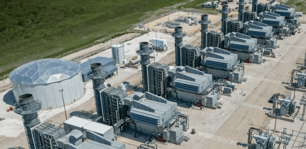
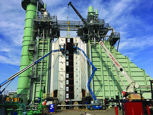
One process that has been developed to remove NOx from emission gases is selective catalytic reduction (SCR). The SCR process is capable of removing over 95% of NOx from the gas turbine exhaust gas. This technology is generally considered a best available control technology, one that represents the most stringent NOx emissions control process that is technologically feasible and cost effective (Figure 1).
 |
| 1. An exhausting process. An exhaust duct of a simple-cycle turbine equipped with a selective catalytic reduction system is shown in this heat-recovery steam generator view. Courtesy: Peerless Mfg. Co. |
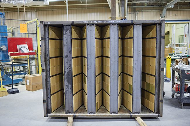
An SCR placed in the exhaust duct of a simple-cycle combustion turbine reduces the concentration of NOx in the exhaust gases by converting NOx into diatomic nitrogen (N2) and water (H2O) molecules, which are not considered pollutants. This reduction is performed with the aid of a catalyst (referred to here as the reduction catalyst) and a gaseous reactant, which is typically ammonia (NH3). Ammonia in the system is often derived from anhydrous ammonia, aqueous ammonia, or urea. The ammonia is added into the exhaust gas containing NOx prior to interaction with the catalyst.
As this mixture of NH3 and NOx passes through the catalyst bed, a high percentage of NOx reacts on the catalyst surface, decomposing into diatomic nitrogen and water molecules, thereby reducing the NOx level in the exhaust gas.
The operating temperature of the reduction catalyst has a critical effect on the NOx conversion efficiency. Depending on the catalyst active component chemical formulation and its substrate, the reduction catalyst is typically utilized at about 850F, and the operating temperature cannot exceed 1,050F for prolonged periods of time. Operating the reduction catalyst at lower temperatures allows for adding more of the active component (typically vanadium oxide) to the catalyst. As a result, the catalyst volume can be reduced and the catalyst life span increased.
Typically, the simple-cycle turbine exhaust gas temperature exceeds the temperature range required by the reduction catalyst, and the exhaust gas must be cooled down. Consequently, in a typical application, simple-cycle power plants require air blowers for injecting ambient air (so-called tempering air) into the exhaust system to bring the exhaust temperature within the operating range of the reduction catalyst.
In addition to forming NOx, the combustion process generates numerous other oxides, some of which are produced as a result of partial oxidation of fuels in the combustion zones with reduced availability of oxygen (O2). An example of these oxides is CO, which is a very stable molecule that is highly toxic to humans. The limits established for CO emissions may require over 90% reduction of raw CO emission levels. Such high conversion levels are possible by oxidizing CO to carbon dioxide (CO2). The oxidation of CO to CO2 is facilitated by the oxidation catalyst, which also reduces concentration levels of unburned hydrocarbons and volatile organic carbons.
The oxidation catalyst is a noble metal–plated catalyst and is capable of operating at 1,200F with efficiency exceeding 90% reduction of CO emissions. As the operating temperature decreases, the efficiency of the oxidation temperature quickly deteriorates, and at 600F the catalyst is capable of oxidizing only about 70% of CO. As a result, there is a temperature window for the efficient utilization of the oxidation catalyst ranging from low efficiency utilization at 500F to high efficiency utilization between 700F and 1,200F.
Whereas the oxidation catalyst achieves higher efficiency when placed and utilized in a higher temperature zone, the operating temperature for the reduction catalyst is limited to about 1,050F. This catalyst maintains its high efficiency at 600F. The operating temperature window is defined by the oxidation catalyst’s minimum effective temperature and by the reduction catalyst’s maximum effective temperature.
Exhaust System Temperature Control Arrangements
Developing control strategies for exhaust gas temperature is challenging. They must consider not only control schemes but also a control methodology that takes into account mechanical and control designs and their effects on the overall efficiency of the simple-cycle system. The control system design should be developed based on site-specific requirements such as the required amount of tempering air and a proper location for the tempering air injection point. To select the proper exhaust temperature control scheme, the simple-cycle plant operating conditions must be carefully evaluated.
Three strategies for injecting tempering air are considered in this article. These strategies differ in where they locate the injection of tempering air. The injection location will have a direct influence on the process control design. For some strategies, the control system can be designed with a single-control loop, whereas for multipoint tempering air injection points multiple control loop designs and their interference should be considered.
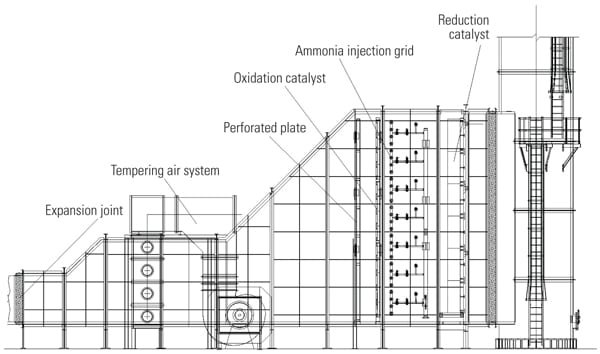
Inject at the Turbine Discharge. One option is to inject tempering air at the discharge of the turbine (Figure 2). Because tempering air is injected at one location, upstream of the emission control catalysts, the exhaust flue gas is cooled down and both catalysts (oxidation and reduction) are maintained at the same operating temperature. However, these catalysts have been developed to control different pollutants and operate efficiently at different operating temperatures. By exposing both catalysts to the same temperature, the catalytic processes are not optimized. Additionally, the overall exhaust system pressure drop may increase when tempering air is injected at the turbine discharge.
 |
| 2. The traditional approach. This schematic depicts traditional tempering air injection at the turbine discharge. The average temperature of the operating exhaust temperature is fed to a controller and compared with the setpoint, which is typically about 850F. Courtesy: Peerless Mfg. Co. |
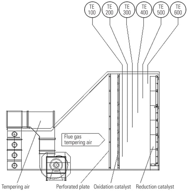
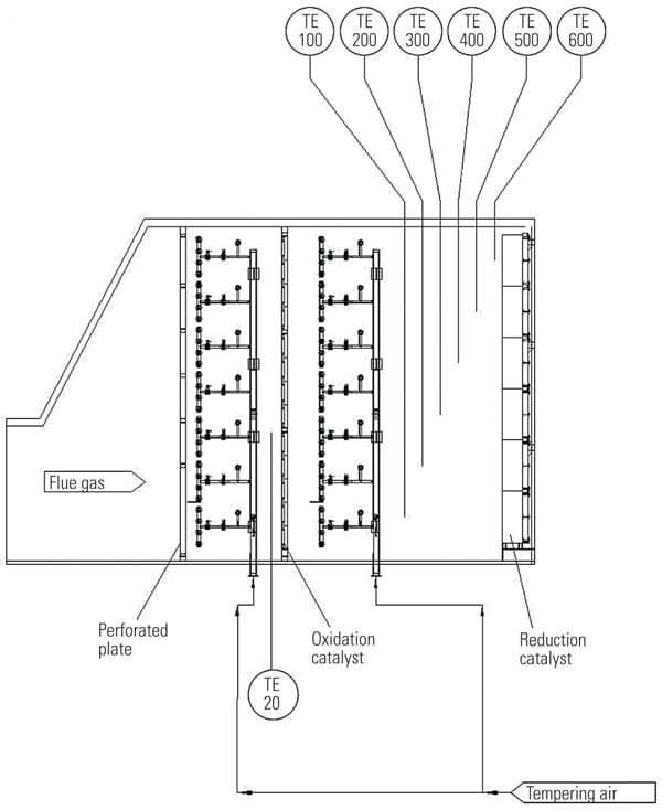
Inject Downstream of the Oxidation Catalyst and Upstream of the Reduction Catalyst. In another approach, tempering air is injected downstream of the oxidation catalyst and upstream of the reduction catalyst (Figure 3). The obvious advantage of injecting tempering air downstream of the oxidation catalyst is that problems with overcooling of the oxidation catalyst are alleviated. This is especially important at partial loads, when the exhaust temperature is low and excessive flow of tempering air causes too low an operating temperature for efficient oxidation of pollutants. By injecting tempering air downstream of the oxidation catalyst, the operating temperature of the oxidation and reduction catalysts is decoupled, and efficiencies of both oxidation and reduction catalysts are maximized.
 |
| 3. Improved injection of tempering air. By injecting tempering air downstream of the oxidation catalyst, the operating temperature of the oxidation and reduction catalysts is decoupled, and efficiencies of both oxidation and reduction catalysts are maximized. Courtesy: Peerless Mfg. Co. |
Note that when tempering air is injected downstream of the oxidation catalyst, the ammonia required for the SCR process can be mixed with tempering air and injected into the exhaust system. In this arrangement the assembly of the ammonia delivery system is greatly simplified.
The control objective for strategies with a single point of injection is to satisfy a given setpoint for the reduction catalyst operating temperature. In this case, the oxidation catalyst temperature is not controlled and either is the same as the reduction catalyst temperature or equals the exhaust gas temperature, depending on whether tempering air is injected at the turbine discharge or downstream of the oxidation catalyst.
When using single-point injection, the exhaust gas temperature is measured at one location at the reduction catalyst. Standard temperature measurement techniques are employed, such as thermocouples with temperature transmitters. To obtain a representative sample, the exhaust temperature is measured at multiple locations. The average value of the operating temperature is calculated and the signal is sent to a controller as a process value. The location of temperature sensors will have a critical effect on determining the actual value of the exhaust gas temperature. Typically, the exhaust gas temperature fluctuates about 25F from the mean temperature.
Given this window of acceptable gas temperatures for effective catalyst operation, the dilution air damper will require a control system that includes feedforward, feedback, or a combination of feedforward/feedback loops.
A feedforward control system will adjust tempering airflow, and corrective action is taken before the output temperature deviates from the setpoint. The required amount of tempering air can also be determined from thermodynamic calculations, taking into account exhaust gas operating conditions and the ambient air temperature. In this control the amount of tempering air will be adjusted with any detected load swings prior to observing any temperature change at the reduction catalyst. Because some of the process disturbances are not measured, and some may even be unknown, the feedforward control is coupled with feedback control to compensate for errors.
A feedback control system is the simplest system to control the tempering air blower output. The average temperature of the operating exhaust temperature, measured as shown in Figure 3, is fed to a controller and compared with the setpoint. The setpoint is typically about 850F. The control system governs the amount of tempering air injected into the exhaust system. The feedback system lags behind changes in the exhaust temperature. The corrective action is not taken until the output temperature deviates from the setpoint. However, this system is ideal where the system oscillations are minimal. The feedback control strategy requires some time before the exhaust gas temperature stabilizes and steady state operation is achieved.
Also note that each proportional-integrative-derivative (PID) control loop must be tuned based on the required speed of response and the absolute value of temperature error when a disturbance occurs. The rate of change of disturbance will have a critical effect on the control loop tuning.
Tempering airflow can be controlled utilizing blower mechanical capacity control or variable speed control. Mechanical capacity control, such as with dampers, can be used to control the capacity of the tempering air blower. Dampers will increase the head and reduce the ambient airflow. By throttling the output, the flow decreases and the head increases, thus some energy savings are achieved.
The other blower capacity control is the variable speed control. With this control both the flow and the head are reduced. This method is more efficient than mechanical capacity control. In both cases, the response from the tempering blower will be different for small and large changes.
In addition, the effects of increased or decreased tempering airflow are influenced by the mixing efficiency of tempering air and exhaust gas. Response time will be site specific, depending upon the particular exhaust system dimensions and the exhaust flow to tempering airflow ratio.
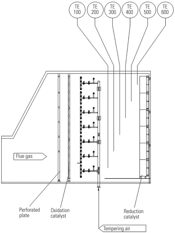
Inject at Multiple Points. A third option is to split tempering air into multiple injection points. In this arrangement, shown in Figure 4, a portion of the tempering air is injected upstream of the oxidation catalyst and the balance of the tempering airflow is directed downstream of the oxidation catalyst into the section between the oxidation and reduction catalyst. In this arrangement, the efficiency of the oxidation catalyst is maximized, and its overcooling at partial loads is prevented.
 |
| 4. Dual arrangement. With this approach, a portion of tempering air is injected upstream of the oxidation catalyst and the balance of the tempering airflow is injected into the section between the oxidation and reduction catalyst. In this arrangement, the efficiency of the oxidation catalyst is maximized and its overcooling at partial loads is prevented. Courtesy: Peerless Mfg. Co. |
As in the second scenario, the operating temperature of the oxidation catalyst is decoupled from the operating temperature of the reduction catalyst and a portion of tempering air may be used as a dilution air for maintaining concentration of the ammonia below the lower explosion limit or as a heating media to evaporate aqueous ammonia.
The temperature of the oxidation catalyst is measured separately, and if too much tempering air is injected upstream of the oxidation catalyst, the flow control valve reduces the amount of tempering air directed to this section. As with previously characterized controls, feedforward, feedback, and feedforward/feedback controls can be used. The loops can be operated and tuned independently. However, a given parameter, such as the exhaust gas temperature at the oxidation catalyst, can be used as the feedforward signal for the feedforward/feedback loop. In this configuration the tempering airflow upstream of the oxidation catalyst would be restricted at partial loads.
This article is based on a paper presented by the authors at the 15th Annual POWID/EPRI Controls and Instrumentation Symposium.
— Dr. Mark A. Buzanowski (mbuzanowski@peerlessmfg.com) is manager of design engineering and Sean P. McMenamin (smcmenamin@peerlessmfg.com) is vice president of Peerless Mfg. Co., in Dallas, Texas.