Pulverizers 101: Part III
Pulverizers prepare raw fuel for burning by grinding it to a desired fineness and mixing it with the just the right amount of air before sending the mixture to boiler burners for combustion. Part I of this three-part report examined the essentials of pulverizer design and performance; Part II discussed the importance of fuel fineness. This final article discusses the importance of air and fuel measurement.
Operating a coal-fired boiler efficiently is all about carefully and constantly managing air and fuel flow. Once pulverized coal flows have been measured, they can be balanced and optimized. Until then, tuning is simply guesswork. The right way to balance furnace fuel flows is to establish solid baseline performance by proper measurement of fuel flow, fineness, and velocity. Only then can all the coal pipes be accurately balanced and followed by a tune-up of the boiler controls.
A Six-Step Program
Efficient furnace performance is absolutely mandatory, regardless of what kind of coal you are firing. The source of the coal matters less than optimizing the fuel system (starting with the pulverizers) and the air system (starting with the primary air fans), which meet at the burner system. Each boiler system must be properly tuned to work with suitably prepared coal, and the process begins with putting the right amount of fuel with the right amount of air in the burner at the right time (Figure 1).
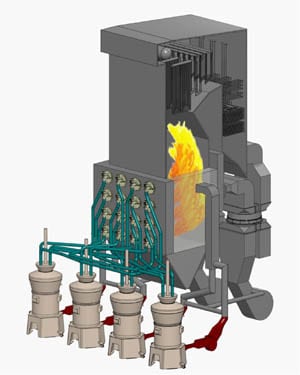
1. Combustion tuning of a pulverized coal boiler begins with balancing the air and fuel flows in the coal pipes from the pulverizers to the burners. Note that each of the coal pipes is a different length. On most boilers, burners are also present on the opposite side of the furnace, adding to the air/fuel-balancing challenges. Courtesy: Storm Technologies Inc.
Tail pipe air quality systems add to the complexity of achieving efficient combustion. For example, many coal-fired plants chose to continue using higher-sulfur coals after they added a flue gas desulfurization, or scrubber, system. Lower-cost coal may save on purchased fuel costs, but the higher-sulfur fuel option poses more of a challenge to plant operators, who must wrestle with the effects of nonhomogeneous mixing of fuel and air, which include reducing atmosphere furnace zones that increase slagging and tube corrosion. The difficulty with properly tuning a boiler experiencing poor combustion is compounded by having only 1 or 2 seconds of furnace residence time to completely combust the fuel.
Balancing fuel flows in a pressurized classifier is best achieved with optimum coal fineness, blueprinted mills, synchronized classifier blade angles/lengths, and a properly calibrated and repeatable optimum air/fuel ratio. Achieving the optimum fuel balance to the burner belt requires very good fuel fineness, determined by current standards, blueprinted pulverizers, and optimized classifier geometry.
The main goal of testing and tuning the coal pipe flows is to tune the entire combustion system to efficiently use every millisecond of the limited furnace residence time available. Here is our six-step program for achieving a satisfactory fuel balance in your boiler burner system.
1. Balance Air-Fuel Flows to the Boiler
So, how do you know that the fuel particles are of required fineness and uniformly distributed?
The first step in balancing the air-fuel mixtures is to ensure that all four fuel pipes, as shown in Figure 2, have the same system resistance (proven by clean air testing). Pulverizer blueprinting is a prerequisite for balanced fuel flow through the burner lines.
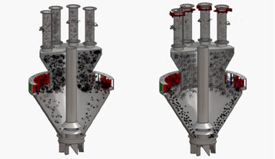
2. Optimized air/fuel ratios in the burner belt begin with a well-turned and well-performing pulverizer. To obtain the specified coal fineness and distribution, the coal flow rate in each pipe must be measured. Source: Storm Technologies Inc.
Keep in mind that coal is about a thousand times denser than air and is a solid. The smaller the particles, the more the solid fuel particles tend to mix in the two-phase mixture of primarily air and coal. Finer particles easily mix with air, as you would observe by performing the following experiment.
Throw a handful of talcum powder into the air on a windy day (talcum’s mean particle size is about 35 microns) and see how it mixes with air—almost like two gases. As do very small solid coal particles, talcum powder has a very low settling velocity. Now repeat the experiment with sand or coarsely ground coal (with a mean particle micron size of about 90 microns) and you will observe that the settling velocity is much faster. That’s why larger particles of coal have a greater tendency to rope (rather than mix with the air) through burner lines and coal nozzles.
2. Run a Clean Air Test
A clean air test is conducted to balance the system resistance of each burner line leaving each pulverizer. Fuel lines must start at the ±2% or better balance of the clean air velocities. The clean air test conducted on each coal pipe is completed by multiple point measurements (usually 24 points of equal areas) using a standard pitot tube (Figure 3). The velocities of the 24-point averages are then plotted on a graph for ease of analysis (Figure 4). Clean air tests must be conducted under steady flow conditions with completely stable system temperatures.
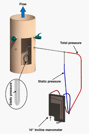
3. The pitot tube measures clean air flow in a coal pipe based on an internal grid of at least 24 individual measurements representing equal flow areas. This measurement is made with no coal flowing into the pulverizers. Source: Storm Technologies Inc.
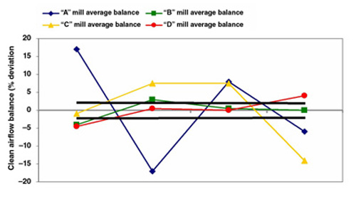

4. On the top is the "as found" variation in the clean airflow for each of the four mills during initial testing on a typical pulverized coal boiler. The bottom chart shows measurements that were repeated on the same system using standard orifices to balance the system resistances of the shorter with the longer coal pipes so that approximately the same quantity of air flows to each mill. The solid black lines represent the acceptable range of operation. Source: Storm Technologies Inc.
Ideally, the system resistances will yield a clean air balance of within ±2% of the mean. This is a good starting point, but by itself, it does not guarantee fuel balance. The fuel balance is dependent upon supplying equal amounts of pulverized coal to each individual coal pipe. Clean air balancing is a mandatory prerequisite to balancing coal flow among coal pipes.
3. Check Dirty Air Velocity Measurements
Dirty air velocity (the velocity of air with entrained coal) measurements are made using a dirty air velocity probe (Figure 5). Velocities should be within ±5% of the optimum air/fuel ratio and fuel fineness after step 2 has been completed.
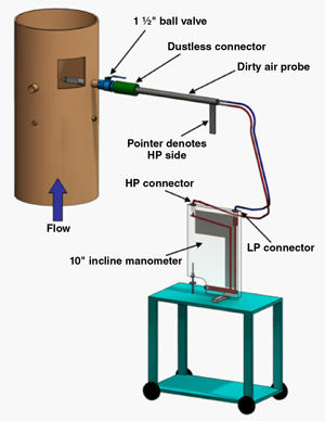
5. A dirty air probe is required when measuring flow velocity in an operating coal pipe. The dirty air velocities of each pipe should be within 5% of the mean of all the coal pipes to achieve uniform fuel flow. Source: Storm Technologies Inc.
It has been our experience that when dirty air velocities are not balanced in each pipe, neither is the fuel flow. Low dirty air velocities are usually accompanied by high coal flows. The lower fuel line velocities at normal fuel flow (dirty air velocities) are attributed to the additional energy required to transport the heavier and denser coal stream (rope) through the heavier coal-laden fuel pipes.
This is why the fuel lines are first balanced on clean air and then followed by dirty air and isokinetic coal fineness measuring and sampling. When fuel flows are uniform to each coal pipe inlet, and the pipes have been previously balanced for similar system resistances, then dirty air velocities tend to be within ±5% of the mean coal pipe dirty air velocity.
4. Calibrate Primary Airflow into the Pulverizer
An accurate flow-measuring venturi or flow nozzle at the pulverizer inlet will allow you to calibrate your optimum primary air/fuel ratio. A typical optimum air/fuel ratio is between 1.6 and 1.8 lb air/1.0 lb fuel.
It’s also important that the primary airflow be measured and calibrated at normal operating temperatures and flows. We call this calibration by the Hot "K" Method (Figure 6).

6. An accurate flow-measuring venturi or flow nozzle at the pulverizer inlet, taking measurements at normal operating flows and temperatures, will allow you to calibrate your optimum primary air/fuel ratio. This approach to measuring airflow is called the Hot "K" Method. The red line is a temperature probe. Source: Storm Technologies Inc.
The primary airflow must be optimized and repeatable for a given coal flow so that the best coal fineness at the best fuel distribution can be produced day in and day out. Varying the primary airflow will change the requirements for fuel fineness, fuel distribution, burner performance, and furnace performance.
The accurate and reliable measurement and control of primary airflows are of great importance to pulverized coal boiler combustion optimization. In fact, in our experience, nonoptimized primary airflow is one of the largest single opportunities for improving the combustion of pulverized coal-fueled boilers.
5. Maintain Fuel Fineness
In general, fuel fineness should be better than 75% passing 200 mesh and less than 0.1% on 50 mesh. Fuel fineness is important for many reasons, including these:
- Lowest possible fly ash carbon content.
- Reduced slagging at the superheater.
- Lowest NOx production.
- Best fuel balance when accompanied by optimized primary airflows, "blueprinted" mills, and balanced clean air resistances.
- More uniform furnace outlet flue gas temperatures.
- Reduced fouling of the convection pass, selective catalytic reactors, and airheaters, and reduced waterwall wastage.
- Reduced reheat desuperheating spray water flows.
- Reduced superheater and reheater tube erosion from excessive sootblowing done to mitigate slagging and fouling with nonoptimum furnace outlet gas temperatures and stratified excess oxygen/temperatures.
6. Sample Fuel Fineness
Next, the fuel fineness in each coal pipe should be measured using an isokinetic sampler, as shown in Figure 7. Fuel fineness is important, but so is fuel distribution in each pipe. We have found some boilers to have some fuel pipes where the fuel flows are several times the average for each of eight pipes leaving a single pulverizer. The fuel line sampling and mass weighted average of fuel fineness must be proven periodically. The best method we have found is an isokinetic coal sampler.
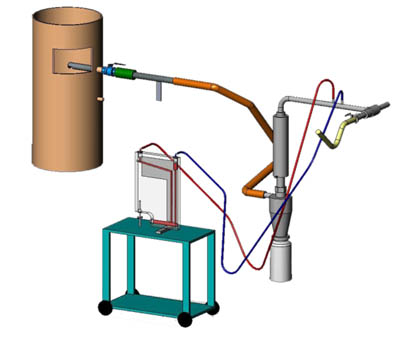
7. An isokinetic probe can be used to sample coal fineness in a coal pipe. A well-performing system will have coal fineness of 75% or more passing a 200 mesh screen; 50-mesh particles should be less than 0.1% in each of the coal pipes. Courtesy: Storm Technologies Inc.
Fuel fineness and distribution are usually optimized for one mechanical relationship to a given primary airflow. Figure 8 illustrates the effects of changing the primary airflow on coal fineness at this same coal plant. A change in the velocities through the mills and classifiers changes the fuel distribution and fineness levels for a given classifier setting. Two pipes show good fineness, and two are poor. Balancing the pipes required lowering the primary airflow to optimum. Fuel balance improved, as did fineness for all four pipes. This is an example of why all of the fuel pipes need to be tested and sampled, and the coal fineness quantified.
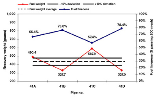
8. The relationship of fuel fineness and distribution can usually be optimized for a given primary airflow. Note the inverse relationship between fuel fineness (blue line) and the amount of fuel flowing through the coal pipe (red line). The fuel distribution and fineness for a given classifier setting are determined by the air velocity through the mills and classifiers. Variation in the fuel mass flow in each pipe should be within ±10% of the overall mean. Fineness must be consistent—no averages should be used. Source: Storm Technologies Inc.
It is common to find one or two coal pipes that provide "good" fineness and two or more that are "poor." Fuel pipes that individually are far different in fineness but average 70% to 75% passing 200 mesh are not acceptable. Averages are irrelevant. Fuel in all of the individual coal pipes must be of specified fineness. The coarse fuel particles in the heavy coal pipes are likely to contribute to slagging, fouling, waterwall wastage, and high carbon content in the ash—among other penalties.
Mills equipped with exhausters tend to amplify nonuniform fuel distribution. This is one reason "coarse cut" riffles tend to amplify fuel imbalances. Fine cut riffles plus good coal fineness can yield improved fuel distribution. Of course, the prerequisite of clean air balancing applies to suction-fired mills also.
A Final Word on Testing
Burner energy inputs are unknown until they are tested and the fuel flows are measured. The fuel flows are not known unless the fuel lines are methodically and precisely balanced on clean airflow resistances and then are carefully tested using "dirty air" velocity probes and isokinetic coal samplers. Corrective actions can then be planned and performed once the fuel flow in each pipe has been measured and the coal has been sampled.
You can’t fix an imbalance if you can’t measure the individual fuel flow through each fuel pipe. And you can’t tune your boiler for optimum performance until fuel flow imbalances are corrected.
—Richard F. (Dick) Storm, PE is senior consultant for Storm Technologies Inc.