Steam turbine designers and researchers agree that for large units (about 300 MW and up) the ramp rates during start-up, large load changes, and other transients are mainly limited by unsteady thermal stresses in the rotors of high-pressure (HP) and intermediate-pressure (IP), or integrated HP-IP cylinders. Cycling thermal stresses or low-cycle fatigue that exceeds prescribed limits can lead to cracking of the rotors.
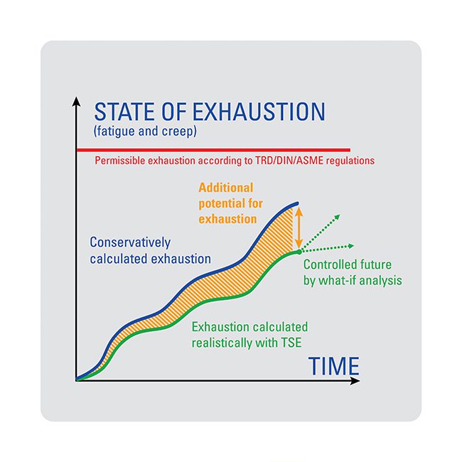
The allowable ramp rates can be found with the help of charts that quantify the turbine life "used up" by each cycle (Figure 1). These "lifetime consumption" charts are calculated for each specific type of HP and IP rotor, taking into consideration the rotor’s radial size (the external and internal radii of the rotor body in the most thermally stressed section), the thermophysical and strength properties of the metal it is made of, and the stress concentrators on the heated surface. The ramp rate for varying steam temperatures is derived from the expected transient operating conditions and from the permissible number of cycles that will give birth to a crack, or from the specific lifetime expenditure, measured in percent per cycle. For less frequent transients, the admissible number of cycles is set lower, resulting in greater rates of heating steam temperature changes. The least number of cycles is assumed for cold start-ups; the greatest number is assumed for load changes in the governed range. Figure 1 also shows a shaded zone that is considered "out of bounds" based on the threat of a brittle fracture of the rotor under the combined action of tensile (centrifugal plus thermal) stresses in its depth, near the central bore or rotor axis.
1. Setting the ramp rate limits. Permissible turbine ramp rates can be derived from ranges in rotor surface metal temperature changes and specific low-cycle fatigue limits. Source: General Electric Co.
What to monitor?
The conditions of heat transfer from steam to a rotor’s surface are much more intense than those for stator components. In addition, the ratio of a rotor’s heated surface area to its mass is much higher than for stator components. As a result, rotors are much more sensitive to variations in heating steam temperatures caused, for example, by load changes or excursions of main or reheat steam temperatures at the turbine entrance.
Operators can therefore expect that if they keep the maximum thermal stresses on a rotor’s heated surface within the allowable range, the maximum thermal stresses in the stator components of the same section will not exceed their design limits. However, the converse may not be true. That’s why it is essential to continuously monitor the actual temperature and thermal-stress states of the rotors to ensure turbine reliability. Because the main and reheat steam temperatures vary independently during transients, it is important to monitor both the HP and IP rotors or, for turbines with integrated HP-IP cylinders, both the HP and IP steam admission rotor sections.
Some turbine designs may impose additional limitations on the handling of transients caused by thermal stresses in casings of the HP and/or IP cylinders. This mainly refers to cold and warm start-ups, as well as shutdowns with forced cooling down of the turbine. These thermal stresses are commonly produced by temperature differences within the casing flanges (across their width and between the wall, flanges, and stud-bolts). Axial temperature unevenness in the casing wall also can be substantial in the neighborhood of intercasing chambers with significantly different heating steam temperatures or the conditions of heat transfer from steam to the casing’s surfaces. In this case, temperature monitoring of high-temperature rotors should be supplemented with metal temperature measurements of the corresponding parts of the high-temperature casings. Also, for some turbine types it is necessary to monitor the temperature and thermal-stress states of the HP valve steam-chests during start-up.
For some large steam turbines it is also desirable to monitor the temperature state of low-pressure (LP) rotors. This is true for turbines with welded or forged LP rotors and elevated reheat steam temperatures, as well as for some large wet-steam turbines of nuclear power plants. Monitoring enables control of the reheat steam temperature (or the steam temperature after the moisture-separators-and-reheaters, in the case of wet-steam turbines) during start-ups without the appearance of inadmissible tensile stresses in the LP rotors (in their steam admission parts) caused by superposition of centrifugal and thermal stresses.
The maximum thermal stress on a rotor’s heated surface is commonly considered to be proportional to a so-called "effective" metal temperature difference across the rotor’s radius in its most-stressed section: between the surface temperature and the integral average temperature in the section. The tensile thermal stress in the rotor depth (on the central bore surface or near the rotor axis) is commonly derived from the entire radial temperature difference between the rotor’s heated surface and depth. The aforementioned metal temperatures and temperature differences should be the object of on-line temperature monitoring for steam turbine rotors. However, because their direct thermometry is too complicated and unreliable, the problem must be solved indirectly by means of physical or mathematical modeling.
Monitoring by modeling
Physical modeling of a rotor’s temperature state implies inserting a so-called "thermometric probe" within the intercasing space. As shown in Figure 2, such a probe conforms to the shape of the rotor sector, and its butt-end is heated by the same steam that sweeps the rotor surface near the modeled section. The probe’s sides are thermally insulated. Using a differential iron-constant thermocouple enables measuring directly the temperature difference (Δt1–2 in Figure 2) between the probe’s butt-end and mid-length. That difference is believed to be close to the effective radial temperature difference in the rotor (between points 1′ and 2′ in Figure 2) to be monitored. Such probes were first introduced by Brown Boveri (now Alstom Power). Later, similar devices were also employed by some other European steam turbine manufacturers.
2. Let’s get physical. Schematic of a thermometric probe, used to physically model rotor metal temperatures. Source: Dr. Alexander Leyzerovich
This proxy method of temperature monitoring has several serious shortcomings, however. One is that the heat transfer conditions from steam to the rotor surface differ considerably from those for heated surfaces of stator pieces, including that of the probe. Another is that heat fluxes from the probe’s sides produce additional methodical errors in modeling. Finally, it is not easy to insert a probe into the turbine’s intercasing space and have it function properly.
Mathematical models based on analog or digital computing techniques do not have these shortcomings. Even rather simple mathematical models provide the divergences between the actual (accurately calculated or directly measured) and monitored radial temperature differences with 10% to 15% accuracy, which is quite acceptable for operation purposes. The use of more advanced calculation techniques enables developers to increase the accuracy and certainty of monitoring by employing more advanced and complicated mathematical models.
Such models can provide, for example, more accurate dependences of the heat transfer conditions on the rotational speed and steam flow of the turbine, and steam conditions within the turbine. They can also take into account the dependence of the metal’s thermal conduction on temperature and some other factors. In particular, it might be also advisable to correct the measured steam temperature for its static and dynamic temperature divergences from the actual heating steam temperature. As applied to LP rotors, mathematical modeling should cover both heating up at start-ups and cooling down during outages.
Mathematical modeling can also be used for arranging the temperature monitoring of some stator components if they are poorly suited for direct measurements of metal temperatures near the heated surfaces. Good examples are the HP valve steam-chests of steam turbines for fossil-fueled power plants and the HP casings of wet-steam turbines for nuclear power plants. In the latter case, the monitoring can rely on regular measurements of steam pressure within the turbine and of metal temperatures on the external, thermally insulated surface.
Today’s more sophisticated mathematical models use a variety of calculation schemes. Most are based on approximate methods of calculating finite differences (more often than not, in explicit form) or approximate transfer functions. In the first case, the model yields a more or less detailed temperature field in the rotor section or zone of interest. In the second case, the model outputs some characteristic temperatures at a few chosen points and the temperature differences between them.
The plant start-up challenge
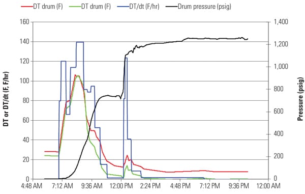
Consider the data recorded during a typical start-up of a 300-MW supercritical-pressure power plant after a weekend outage (Figure 3). The plant is equipped with a one-bypass start-up system. Along with spray attemperators for main steam, including start-up attemperators placed directly in the main steam lines downstream of the superheater, the boiler’s reheater is furnished with a steam bypass employed as a start-up attemperator. The turbine has separate high-pressure (HP) and intermediate-pressure (IP) cylinders, and HP valves are located separately from the turbine and are connected to the HP cylinder with crossover pipes.
3. Test yourself. The high-pressure and intermediate-pressure rotor temperatures of a 300-MW supercritical-pressure steam turbine were recorded during a warm start-up after a weekend outage. Can you identify the operating errors made during the start-up? Source: Dr. Alexander Leyzerovich
Study the start-up sequence illustrated in Figure 3. The diagram reveals some obvious errors committed by the operator. Can you identify them? (No cheating; the answers follow below.)
Explore the data
The recorded data indicate that even though the start-up went rather satisfactorily on the whole, there were some instances when the monitored temperature differences in the rotors exceeded the set limitations. One obvious mistake the operator made was allowing steam to enter the HP cylinder before the HP crossover pipes were completely preheated. This produced a temperature spike in the HP cylinder. Another error was admitting steam to the IP cylinder before the hot reheat steam lines were properly preheated. This also produced an unacceptable temperature spike in the IP cylinder.
Finally, after the generator was synchronized and the turbine accepted the initial load, the main spray attemperators were improperly engaged, causing another temperature spike in the HP cylinder. At the same time, the operator delayed opening the bypass valve of the boiler’s reheater for 5 to 7 minutes. The result was an increase in the radial temperature difference in the IP rotor beyond the limit. As soon as the reheater bypass was opened, the reheat steam temperature fell and the monitored temperature difference in the IP rotor returned into the permissible range.
At this plant, post–start-up analysis of the recorded data was used for teaching and training of operators to prevent repetition of their errors. Here’s hoping that you learned as much as they did.
The plant start-up challenge
Consider the data recorded during a typical start-up of a 300-MW supercritical-pressure power plant after a weekend outage (Figure 3). The plant is equipped with a one-bypass start-up system. Along with spray attemperators for main steam, including start-up attemperators placed directly in the main steam lines downstream of the superheater, the boiler’s reheater is furnished with a steam bypass employed as a start-up attemperator. The turbine has separate high-pressure (HP) and intermediate-pressure (IP) cylinders, and HP valves are located separately from the turbine and are connected to the HP cylinder with crossover pipes.
3. Test yourself. The high-pressure and intermediate-pressure rotor temperatures of a 300-MW supercritical-pressure steam turbine were recorded during a warm start-up after a weekend outage. Can you identify the operating errors made during the start-up? Source: Dr. Alexander Leyzerovich
Study the start-up sequence illustrated in Figure 3. The diagram reveals some obvious errors committed by the operator. Can you identify them? (No cheating; the answers follow below.)
Explore the data
The recorded data indicate that even though the start-up went rather satisfactorily on the whole, there were some instances when the monitored temperature differences in the rotors exceeded the set limitations. One obvious mistake the operator made was allowing steam to enter the HP cylinder before the HP crossover pipes were completely preheated. This produced a temperature spike in the HP cylinder. Another error was admitting steam to the IP cylinder before the hot reheat steam lines were properly preheated. This also produced an unacceptable temperature spike in the IP cylinder.
Finally, after the generator was synchronized and the turbine accepted the initial load, the main spray attemperators were improperly engaged, causing another temperature spike in the HP cylinder. At the same time, the operator delayed opening the bypass valve of the boiler’s reheater for 5 to 7 minutes. The result was an increase in the radial temperature difference in the IP rotor beyond the limit. As soon as the reheater bypass was opened, the reheat steam temperature fell and the monitored temperature difference in the IP rotor returned into the permissible range.
At this plant, post–start-up analysis of the recorded data was used for teaching and training of operators to prevent repetition of their errors. Here’s hoping that you learned as much as they did.
Monitoring during operation
All of the above-mentioned methods of steam turbine temperature monitoring have been used in long-term operational practice at many power plants. In particular, there is a long and detailed history of applying analog and digital devices for temperature monitoring of the HP and IP rotors at standard Soviet 300-MW supercritical-pressure steam turbines. Some of these devices have been in service for over 25 years. Recorded data of such regular monitoring for sister turbines at several power plants were used to calculate specific lifetime expenditures of rotor metal caused by low-cycle (thermal) fatigue as applied to characteristic cycles of transients.
At some power plants, the transients ran practically without regard to temperature monitoring of the rotors; at others, the transients were run with the feedback based on monitoring data. The results of these calculations (see table) illustrate that in the first case the values of specific low-cycle fatigue were up to two orders of magnitude greater than in the second case. It’s also important to note that, without temperature monitoring of the rotors, operators and engineers usually failed to notice the operational errors (see box) that caused undesirable steam temperature excursions, inadmissible thermal stresses in the rotors, and resultant increased lifetime expenditures. With on-line temperature monitoring of rotors, the turbine transients were endured with greater load change rates and lower fuel losses and turbine lifetime expenditures.
Prerequisites for modeling
The model outputs are useful only if the model uses good input data, such as the main steam temperature when modeling the temperature of a turbine rotor. In many cases, it isn’t easy to measure the actual steam temperature near the most thermally stressed section of a rotor. In such cases, the best option is to calculate the heating steam temperature by relying on the regular steam temperature measurements at the turbine entrance. This can be done without excessive errors for IP rotors and HP rotors of turbines with throttle steam admission control. But for turbines with nozzle-group control, this is impossible because of unavoidable great losses in accuracy. To monitor the temperature state of LP rotors, the turbine should be furnished with measurement(s) of steam temperature after the IP section (for example, in the LP crossover pipes).
There are computing devices for temperature monitoring of turbine rotors that rely on measuring the heated surface temperature of the turbine casing via a "thermometric probe" installed in the casing. This temperature is considered representative of the rotor surfaces, and the temperature difference characterizing the rotor’s thermal-stress state is calculated based on this temperature. It would be much more reasonable to arrange for measuring the heating steam temperature and to calculate the actual rotor temperature on the heated surface with the use of known dependences of the heat transfer conditions.
Even though most modern large steam turbines are provided with temperature monitoring of their rotors, plenty of turbines have not been furnished with the means for such monitoring—or these means became obsolete. It’s noteworthy that many of these turbines have to operate in a cycling mode, when temperature monitoring of rotors is especially important. Many of these turbines are now retrofitted to extend their lifetime and improve their efficiency. Retrofitting presents a good opportunity to arrange for monitoring based on mathematical modeling. This can be done, for example, with the use of the power plant’s computerized data acquisition system or an additional PC-based local surveillance subsystem.
—Dr. Alexander S. Leyzerovich is an independent power engineering consultant with more than 40 years’ experience in researching, analyzing, and improving the operating conditions of steam turbines at fossil-fueled and nuclear power plants. His latest book, Steam Turbines for Modern Fossil-Fuel Power Plants, will be published by Fairmount Press Inc. later this year. He can be reached at alexleyzerovich@yahoo.com.