For years, original equipment manufacturers (OEMs) of heat-recovery steam generators (HRSGs) have supplied distribution grids (DGs) as a means for controlling the undesirable velocities, temperatures, spin angles, and pulsations generated by certain gas turbines. In the past, the combustion turbine OEMs readily provided information about the velocity profiles of these units, but in recent years that information has been increasingly more difficult to obtain, let alone substantiate.
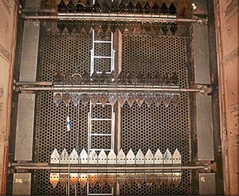
The fact that some turbine installations produced large disturbances led HRSG OEMs to take the strong-arm approach of adding a distribution grid. The presence of a DG can produce a pressure drop of up to 2 inches (water column), adversely affecting the turbine’s performance and/or necessitating an increase in the size of the HRSG. Although the use of guide vanes has proved successful, the technique also proved to be more black art than science. The number of failures that have resulted has made many HRSG users averse to using guide vanes.
The challenge for designers of HRSGs is to develop analysis tools that allow them to thoroughly understand the fluid dynamic storm raging at the entrance to the HRSG and use those tools to develop designs that reduce the flow disturbances and induced vibrations. As a result, many manufacturers of burners and HRSGs either have purchased software programs or contracted for computational fluid dynamics (CFD) analysis or cold-flow modeling of the problems (see box).
This replacement of intuition by science is a positive development; eliminating flow and vibration problems requires a comprehensive understanding of the interaction between fluid dynamics and installed hardware. Although the level of that understanding has increased significantly over the past decade, some key design information still remains a closely guarded secret today, and some OEMs are even attempting to patent certain devices for changing flow distribution.
Optimizing design velocity
The amplitude and uniformity of gas velocity through sections of the HRSG affect not only the unit’s heat-transfer and burner operation, but the performance of downstream emissions control systems as well. The desirability of reducing an HRSG’s footprint and materials costs has led all OEMs to continue pushing the design envelope. But some may have gone too far; there are at least two OEMs whose success with aggressive ductwork configurations have raised questions about what is proper gas flow performance.
Together, proper design and careful analysis can overcome most duct design challenges by evening out the distribution of gas flow across the heating surface of a burner. Every burner has an ideal approach velocity and flow distribution. Louisville-based Vogt Power International, Inc. prefers not to use increased baffling to provide them because doing so can cause reliability problems. For example, some HRSG OEMs use long runners to guide flow to burners located in large cross-sectional areas of the inlet duct. But such runners are susceptible to failure due to gaps in support along their length, turbulence, uneven thermal growth, etc.
Another design challenge that CFD analysis is particularly good at meeting is a common one: minimizing the footprint and interconnecting ductwork of a gas turbine–HRSG combination. For one particular installation of a General Electric 7FA turbine, Vogt used CFD to minimize locally high near-wall velocities and backflow, reducing ductwork by 30% (Figure 1). On another project with the same goal, another OEM reportedly designed a duct that left the top 20% of heating surface open, reducing the effectiveness of the design and failing to meet performance goals.
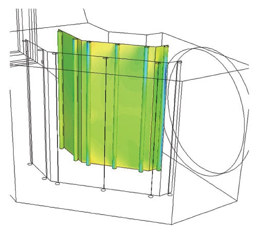
1. Go with the flow. Flow velocity distribution in the entry duct can vary significantly and can seriously impact HRSG performance. Computational fluid dynamics (CFD) analysis can determine the most effective design and placement and design of a distribution grid.
Courtesy: Vogt Power International
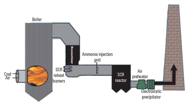
A final bit of practical advice in the field of HRSG burner design: Don’t be tempted to increase the burner firing rate to increase steam production. Doing so either will worsen the distribution of gas flow or cause premature failure of pressure parts or liners by overheating them. In some jurisdictions, increasing the firing rate also will increase the ammonia slip of the selective catalytic reduction (SCR) system downstream of the HRSG above permissible limits.
Following are some of the parameters that Vogt takes into account when configuring HRSG inlet duct geometry:
- The gas turbine’s exhaust geometry and direction.
- The dimensions of the heating surface module.
- The location of duct burners.
- The mass flow rates and average velocities of the gas turbine’s exhaust.
- The mass flow distribution at the entrance to the heating surface.
- Local velocities within the inlet duct: Near duct walls, and at the entrance to the first heating surface.
Fluttering tubes
Field reports suggest that flow- or pressure-induced vibrations from a gas turbine may have caused or contributed to premature failures of relatively new interconnecting ductwork. As a result, OEMs of HRSGs have begun to offer ductwork designs tailored to a particular gas turbine. Vogt’s experience has been that using certain ductwork designs with certain turbines whose inlet blades are water-washed can also cause problems.
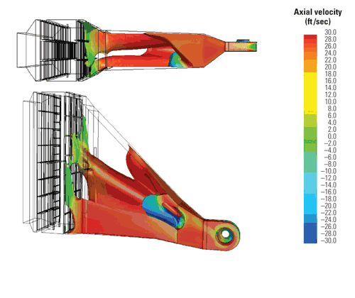
As mentioned, many turbine users have experienced premature failures of guide vanes. They have responded by removing them. But because some users say that removing the vanes did not adversely affect HRSG performance, vanes’ effectiveness in some applications could be considered questionable. Vogt’s contribution to this debate is to suggest using smaller vanes (if the ductwork is amenable) because they seem to last longer than larger ones. Optimizing the design and size of any vane requires a thorough understanding of three variables: its anchoring mechanism, the forces on it, and the delta pressure across the surface of its blades. Figures 2 and 3 illustrate the contributions to Dp of backflow, swirl, and the direction of gas turbine discharge.
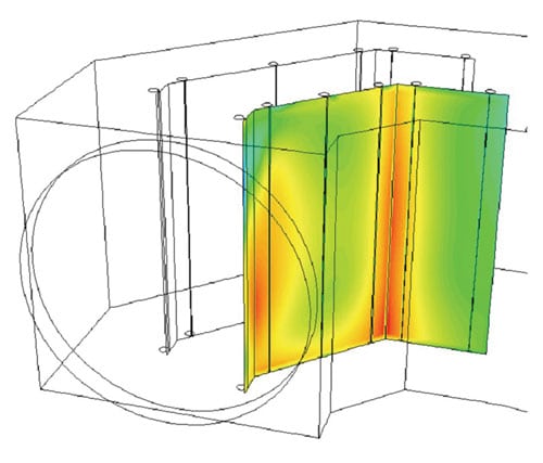
2. Blowin’ in the wind. Pressure distributions on the windward and leeward side of inner turning vanes.
Courtesy: Vogt Power International
3. Turning point. Turning vane designs can significantly affect flow distributions in downstream ducts. Courtesy: Vogt Power International
Vogt has learned from its CFD analyses that these relationships and contributions are easily misunderstood and miscalculated. Sometimes the solution is closer attention to the construction of vanes. Changes in industry practice—today’s use of stitch welds rather than seal welds for transitions, for example—confirm the benefits of this attentiveness. Similarly, in bridge construction, rivets were commonly used in lieu of welds; because rivets lack a fixed point, they cannot transmit a moment. These changes in attachment practice have proven capable of reducing the amount of cracking in inelastic structures.
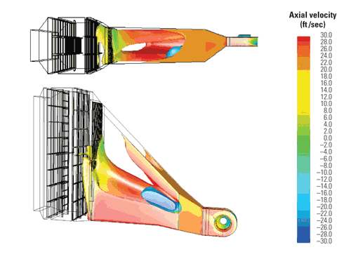
Figures 4 and 5, respectively, depict the flow contours and velocity distributions of a Vogt inlet-duct design. As part of the design, we generally attempt to minimize vibration and damage to liners by predicting near-wall velocities, limiting high local velocities, and minimizing large regions of backflow—particularly backflow with large velocities.
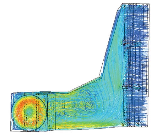
4. All shook up. CFD results illustrate the contours and flow path lines (colored by temperature) in an HRSG entry duct. Courtesy: Vogt Power International
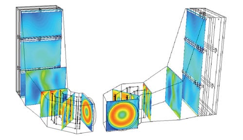
5. Fast and furious. Velocity distributions confirm the final duct design.
Courtesy: Vogt Power International
Losing pressure—and NH3
Among the steps that Vogt takes to minimize HRSG gas side pressure drop (GSPD) are the following:
- Design inlet ducts for maximum pressure recovery.
- Design distribution grid(s) and place them where they will be the most effective over the largest operational range and with the smallest GSPD penalty.
- Achieve the best velocity distribution across burners (both up-front and interstage) with minimum GSPD and/or distribution equipment.
- Use and/or modify upstream modules to improve gas distribution.
- Improve distribution by making use of catalyst layers’ "built-in" GSPD. Here, it’s important to realize that plate and honeycomb catalysts of the same effectiveness exhibit different pressure drops.
- Model and design stack breaching to minimize GSPD. Often, overlooking this design issue can result in the unwanted addition of as much as 1/3 of an inch of pressure drop.
- Maximize the "stack effect."
In this area, one of Vogt’s most notable successes to date has been our ability to "shoehorn" an emissions system into an existing HRSG without a spool piece. In other cases, the CFD analysis and solution resulted in a dramatic reduction of ammonia slip—which, incidentally, many believe is more harmful to the environment than NOx.
The final word on this subject has to do with emissions guarantees. A few years ago, a customer requested guarantees of 1 ppm for both NOx and ammonia slip from an HRSG. Although the company met them, the customer questioned both the accuracy and placement of the measurement device. In yet another similar case, an outside lab was required to "prove" that emission guarantees were met. Be forewarned: the location of a probe relative to its fluid dynamics can make or break a guarantee. This is another reason why a clear understanding of HRSG gas side fluid dynamics is mandatory today. Variations in inlet duct design can make a dramatic difference in reported results (Figure 6).
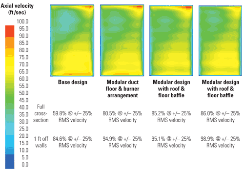
6. Terminal velocity. Comparison of axial velocity distribution on a cross-section between the distribution grid and burner. Courtesy: Vogt Power International
Lessons learned
CFD analysis of the exhaust gas flow distribution in the inlet ductwork of combined-cycle power plants has contributed both to lowering their operating costs and improving their emissions performance. Here’s an example.
At one site where a gas turbine was upgraded, the plant owner simultaneously replaced both the CO and SCR catalysts to withstand its higher exhaust temperatures. After the retrofits, both NOx and CO emissions were within permitted limits, but still above expected values. Operators found that overspraying was required to reduce NOx to the desired value of 3.0 ppm at 15% O2, but that doing so increased ammonia slip at the stack to an unacceptably high level. Vogt was asked to find a long-term solution to the problem.
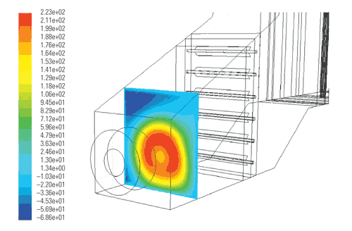
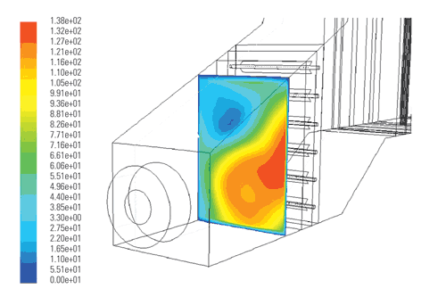
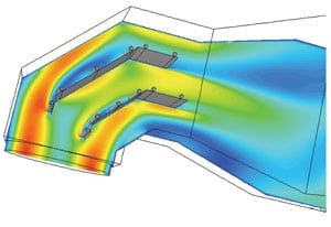
The company’s investigation and analysis confirmed that the poor emissions performance was caused by highly biased gas flow distributions at the entrance to the CO catalyst modules and the ammonia injection grid. Using multiple models to evaluate alternate configurations of flow control devices, Vogt designed a single distribution grid and concluded that locating it upstream of the CO catalyst modules would improve flow distributions at both the CO and SCR catalysts and the ammonia injection grid. Field tests confirmed that the new grid significantly improved emissions performance and reduced both required ammonia injection flows and ammonia slip values eight-fold. Figure 7 shows the "before" and "after" analyses.
7. Off the grid. Constant value surface velocity before (top) and after (bottom) CFD analysis and design of a distribution grid. Courtesy: Vogt Power International
The CFD analysis program at Vogt Power International Inc. is managed by Tony Thompson. A similar program is managed at Riley Power Inc. Both Vogt Power and Riley Power are subsidiaries of Babcock Power International. Their assistance in the preparation of this article is appreciated. All of the CFD figures referenced in this article were completed using Fluent 6 flow modeling software from Fluent Inc. (Lebanon, N.H.).