If your facility has recently seen an upsurge in bearing failures on boiler feedwater (BFW) pumps, you are not the only plant experiencing these unnecessary and costly failures. The failure causes are often elusive, which is why plants have so many unresolved repeat failures.
During an economic downturn, maintenance outlays and training funds frequently are among the first to be curtailed. Maintenance managers are then able to authorize only those repairs they deem absolutely necessary to keep the plant running. In effect, these decisions often encourage treating the pump failure symptoms and discourage looking for the true root causes of failures. In time, the plant will incur higher maintenance expenditures and an increase in forced outages caused by deferred maintenance. The underlying causes of pump failures must be determined and corrected if plants are to continue reliable operation.
Why Bearings Go First
One plant component that is often the victim of deferred maintenance is the boiler feed pump, especially those in the 200-kW to 2,000-kW range. The effects of deferred maintenance often appear as increased wear and tear on lubricated components. For example, we currently see fewer BFW pump bearings reaching the end of their design life.
Also, and in spite of using better lubricants and installing bearing protector seals, pump bearings tend to be the parts that fail first. Seeking to avoid bearing problems, many facilities have placed greater emphasis on vibration-monitoring programs, allowing operators to initiate pump shutdown a short time before disaster strikes. Having shut down just in time, people then congratulate themselves for accomplishing what management has decreed; that is, repairs were deferred until absolutely necessary and only the glaringly defective parts got replaced.
Deferring a full repair does not address the root cause of the failure, and repeated failures put both equipment and human resources at risk. Although the failed part is the weakest link in the component chain and needs to be replaced, something else is pushing the weakest link toward premature failure. We often forget that repeat failures are the precursor to far more serious events. More failed pumps per time period shorten the mean-time-between repairs (MTBR) metric. This is most noteworthy because statistics, described in the Pump User’s Handbook: Life Extension, found that a serious fire occurs for every 1,000 pump failures.
Underlying Causes of Failure
Some facilities that are worried about unexpected BFW and other large pump outages decide to operate two or more pumps in parallel. However, for reasons of gaining power efficiency, the performance curves of many of these pumps were originally designed to be relatively flat at flows approaching shutoff. The resulting pressure rise from operating point to shutoff is then either insufficient or nonexistent (Figure 1). As one or more pumps are operating too close to shutoff, shafts deflect and bearings are overloaded. The oil film that must separate bearing rolling elements from stationary elements thins and heats up the bearings, causing a vicious failure cycle. High load, a thin oil film, and high metal temperature combine to result in premature bearing failure. Depending on the bearing cage type, these failures range from gradual and detectable to sudden, difficult-to-detect-in-advance, and just plain catastrophic.
Running fewer pumps in parallel would result in each pump operating closer to its best efficiency point (BEP). In contrast, operating too many pumps often causes one or more to operate in the prohibited low-flow range, especially if their respective head-capacity (H-Q) curves (Figure 1) are not identical. Internal recirculation and progressive wear increase the difficulty of successfully operating pumps in parallel. Mechanical parts distress and seemingly small deviations from the least-risk geometry of best available designs now converge, and the BFW pump will become involved in a string of seemingly random failures. Impeller erosion and loss of internal clearances will have occurred as well.
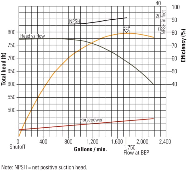 |
| 1. On the level. A typical “flat” pump performance or head-capacity curve with undesirable low-flow characteristics is illustrated. The best efficiency point (BEP) is found at 1,750 rpm. Source: Heinz P. Bloch |
Internal wear and operation at low flow also cause pump cavitation. The impeller regions subjected to a given pressure will vary with progressive wear. Prevailing pressures multiplied by effective impeller areas will generate a thrust force. An increase in this thrust force can greatly contribute to bearing failures because bearing life varies inversely and exponentially with load. Moreover, on BFW pumps with sleeve bearings and associated shaft-driven worm gear lube supply pumps, excessive thrust often leads to worm wheel damage and loss of lubrication.
Pump operators and reliability professionals need to pause and consider each of these risk factors independently and in total. Pump owners must accept that, as several risk factors accumulate, there will be a time when one seemingly small deviation could result in catastrophic pump failure and perhaps cause an outage of the entire plant. Therefore, it should be a priority to examine all probable causes and factors that have recently combined or contributed to costly repeat failures of BFW pumps.
Simply put, operating in the low-flow range forces BFW pumps to run in the flat portion of the H-Q curve. By the time pressure sensors signal a small pressure difference in the flat portion of the curve and control action is initiated, large differences in throughput will have occurred. Flow control and load sharing are difficult in the flat portion of a pump performance curve, and long-term satisfactory pump operation is simply not possible in the forbidden low-flow range.
Rebuilding and Upgrading Are Urgently Needed
The best possible remedial action is to rebuild and upgrade all the plant’s BFW pumps, for example, and to then use controls—automated or manual—that ensure pump operation in the steep region, or close to BEP. The next step is to couple the upgrades with good operator training that reinforces the BFW pump system design rationale and proper operating procedures.
Rebuilding BFW pumps affords an opportunity to upgrade older BFW pumps to current designs and modern materials, such as high-performance polymer-based wear rings and throat bushings. Rebuilding all pumps to original equipment manufacturer (OEM) specifications should be entrusted to either the OEM or a reputable pump rebuilder.
Should you elect to rebuild your key process pumps, consider adopting the following criteria when preparing your purchase order specifications.
For example, many process pumps are equipped with slinger rings that supply oil to the bearings. To perform well, these oil rings (slinger rings) must be concentric within 0.002 inches (0.05 mm) and have a bore finish reasonably close to 32 RMS. Oil rings will not survive long if the shaft system is not truly horizontal or if the depth of immersion in the oil is either too much or too little. Although an ISO Grade 32 lubricant is required on pumps equipped with sleeve bearings, mineral oils with this viscosity grade are seldom satisfactory for BFW pumps with rolling element bearings. In theory, rolling element bearings will benefit from ISO Grade 68 mineral oils. This thicker ISO grade is required for rolling element bearings, and major bearing suppliers recommend ISO Grade 68 mineral oils up to 176F. However, using the thicker ISO Grade 68 mineral oil will slow down the oil slinger rings and will, furthermore, risk depriving sleeve bearings of the oil wedge on which the shaft must ride.
Special issues and potential problems thus arise if, in any pump, both sleeve type and rolling element bearings share the same bearing housing. In essence, viscosity is of greatest importance, and each bearing type fails if there is prolonged metal-to-metal contact. To prevent this contact, the oil film has to be thicker than the asperities (the surface roughness) in the bearing and journal surfaces. The oil film must also be thicker than an occasional dirt particle traveling in the oil. Most importantly, the oil needs to be properly applied and must form a suitable film on the surfaces where such a film is most needed. To make a long story short, a lubricant with all required performance attributes, including film strength and film thickness, must, at the same time, allow slinger rings to function properly.
Only well-proven synthetic ISO Grade 32 lubricants will satisfy all of these requirements. A preferred supplier usually formulates such lubricants from a PAO/Diester synthetic base oil to which an ionic bonding agent has been added. The oil will have to be viscosity Grade 32 and the particular synthetic ISO Grade 32 formulation must give users the protection and film thickness/film strength properties of ISO Grade 68 mineral oils. Though these properties may not be needed elsewhere in your facility, their use is appropriate in BFW pumps that have recently and unexpectedly proven repair-intensive.
While troubleshooting lubrication issues on existing pumps, sludge in pump bearing housings is often found. Water acts as a catalyst that promotes sludge formation. Sludge is thus often the result of water and atmospheric dirt, in addition to oil ring (slinger ring) debris. Exposure to airborne particulates is unavoidable in some environments, and water intrusion is possible in other environments. Another possible source of water is from cracked water jackets. There is some irony in that situation, because with rolling element bearings, cooling water may not be needed in the first place.
The troubleshooter should also take care not to mix two “virtually identical” oils from different suppliers. There is ample evidence that some oil suppliers skimp on the amount and/or quality of additives to reduce cost. If you are buying lubricants based on lowest cost, then you are encouraging suppliers to provide a “commodity product,” and commodity lubrication products may not be able to provide the reliability desired.
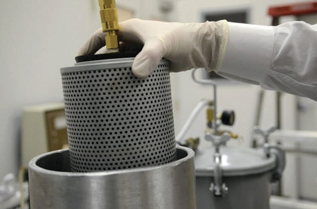
During a recent plant visit, an oil slinger ring that had been removed from a BFW pump after the latest pump failure was measured. Instead of staying within the allowable eccentricity of 0.002 inches, this ring was about 0.06-inch eccentric—30 times the allowable value. The ring was abraded on one side; it also showed very serious discoloration, like that shown in Figure 2. If you use slinger rings, make your selection based on quality, not price. Good ones will have gone through an annealing step before finish-machining. Again, be certain to subject slinger rings to rigorous specifications and quality control.
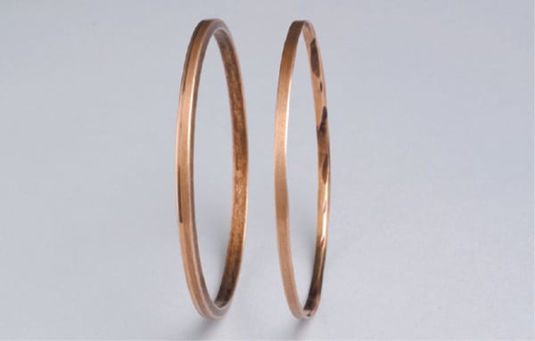 |
| 2. New slinger available. This photo shows a new slinger ring (left) next to an abraded slinger ring (right). Courtesy: Heinz P. Bloch |
On pumps furnished with rolling element bearings, avoid slinger rings by insisting on bearing housings configured to accept solid flinger discs or at least a lubricant application method other than slinger rings. Also, slinger rings can become dislodged when the equipment is transported from a factory or shop to an installation site and become lodged between shaft and ring locator pin or some other housing component.
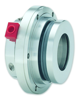
When a pump does require an overhaul, systematic upgrading is practiced by best-of-class companies on every pump that enters their repair shop. Bearing protector seals are among the first upgrade components. However, some widely used bearing protector seals have a dynamic O-ring located directly across from a sharp-edged groove (Figure 3, top left). Under certain operating conditions, this O-ring will abrade, and elastomer flakes will contaminate the lubricant, possibly causing “black oil.” Others use V-rings for unitizing rotor and stator into a single package (Figure 3, top right), but these then tend to induce frictional drag. More recent designs (Figure 3, bottom image) manage to avoid such risks, and upgrading to the least-risk bearing protector seal makes much sense to the reliability-focused.
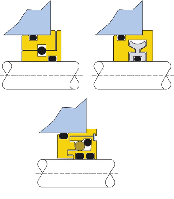 |
| 3. Three bearing housing protector seals. Pay close attention when specifying pump O-rings. Some configurations risk O-ring degradation (top left) due to contact with sharp grooves. Others use a V-contoured ring (top right) that tends to increase frictional drag. Look for optimized designs (bottom) when choosing an O-ring. Source: Heinz P. Bloch |
Systematic upgrading of BFW and other important process pumps also includes retrofitting only the very best constant level lubricators. This implies that reliability-driven facilities would use pressure-balanced models that typically cost $30 to $50 more than the traditional nonbalanced models found on most process pumps.
True reliability-focused purchasers have justifiable concerns with traditional and failure-prone means of lubricant delivery. Communicate with a pump manufacturer when vulnerabilities of certain pump designs are discovered. On their part, operators must use rigorous checklists that lead to better installation procedures, verification of adequacy before start-up, and adequacy while running and when doing root cause failure analysis. Reliability improvements are a shared obligation that cannot be disregarded by either party.
—Contributed by Heinz P. Bloch (hpbloch@mchsi.com), machinery reliability consultant and author of 18 books on practical machinery management, maintenance, and repair.