Once the condenser tubes are designed, selected, and purchased, the final step in a retubing project is to remove the old tubes and install the new ones. The success of this project is very dependent upon attending to quality control, following proper procedures, using the right tools, and having a highly skilled workforce.
A condenser retubing is a major maintenance project, occurring perhaps once in a unit’s lifetime. It is not a routine project, although many of the installation steps involve activities that are repeated tens of thousands of times. The retubing project is usually a part of a major unit overhaul and is always (it seems) the critical path of the overhaul schedule.
Just as challenging as the compressed time schedule is the unknown material condition of portions of the condenser that were not inspected prior to the outage. The actual material condition of the condenser is only revealed when the waterbox is opened, the tubesheet is visible, and the steam side is fully exposed. Contractor estimates for material cost and labor productivity are made in advance of the outage and often do not match the true condition of the condenser. Frequently, the extent and type of tube fouling and deposits, tubesheet and tube strength degradation, the extent of corrosion and erosion, and the internal structural condition and alignment are unknown until a complete inspection is conducted when the project begins.
Another uncertainty is the tubesheet and support plate resistance to tube removal. How difficult and time-consuming it will be to remove the tubes is usually unknown until that first tube is removed. Yet the contractor is still expected to translate a stack of drawings, specifications, raw materials, and thousands of tubes into a like-new condenser, often in record time.
Schedule-Driven Processes
The condenser is designed to last the life of the power plant and has no moving parts, yet it has tens of thousands of mechanical joints and hundreds of thousands of square feet of very thin surface area. The condenser operates in a strong vacuum while withstanding the impact of millions of pounds of steam each hour on the outside of the tubes and millions of gallons of cold water flowing through the tubes.
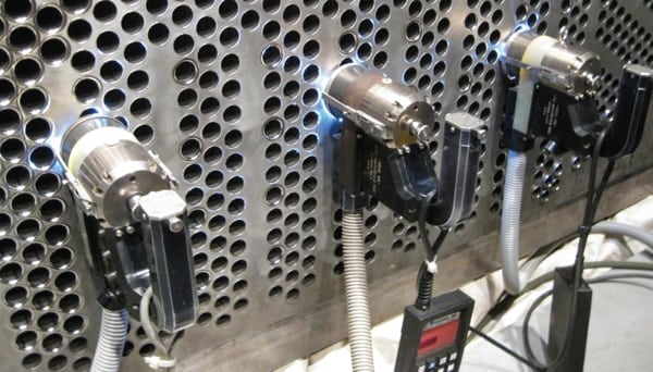
A good joint made between the condenser tube and tubesheet is critical to preventing leaks. The success of a retubing project often depends upon making that joint secure tens of thousands of times. To maintain that vacuum, all these components and fabrications must seal tight and allow no air in-leakage and no cooling water leaks (Figure 1).
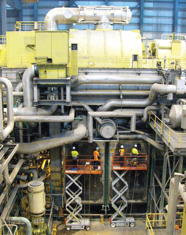 |
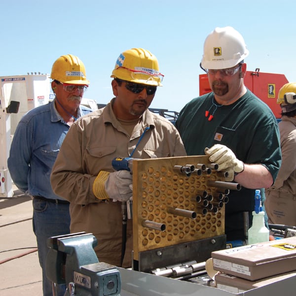
| 1. Repetitive task. The condenser, usually located beneath the low-pressure steam turbine exhaust, may contain 50,000 or more tubes. A condenser overhaul requires removal and replacement of each tube, a labor-intensive job. Courtesy: Conco Systems Inc. |
A condenser retube project is also very labor-intensive, often consuming 5,000 to more than 50,000 man-hours for a large unit. Although the task is repetitious, significant training and testing is required for the staff entrusted to do this job, especially for those responsible for the tubesheet hole preparation and tube expansion processes.
Managing Processes and Manpower
In many ways, a condenser retubing is a large material-handling project. Old tubes are removed and salvaged as the new tubes are moved into place. Hundreds of tons of tubes are replaced tube by tube, 20 to 30 pounds at a time. A single set of retubing tools will produce perhaps two tons of flattened and chopped tube scrap per shift.
The project schedule is based primarily on the number, configuration, and size of the tubesheets, and the time allotted during the unit outage. A crew of five or six plus equipment is usually able to work on a narrow tubesheet. Two crews can operate side-by-side on wider tubesheets. The overhaul schedule will determine whether one or two daily 10-hour shifts are required. The normal work schedule is six days per week. A smaller 10,000-tube condenser will require two shifts per day for two or three weeks. A 40,000-tube condenser may require two daily shifts for three to five weeks. A well-trained, fully equipped crew can remove and replace 600 to 800 tubes per shift and, later, stick tubes at about the same rate. Tubesheet and waterbox coating will add seven to 10 days at the end of the project.
The three primary activities during any retubing project are tube removal, tubesheet and support plate hole preparation, and tube installation and expanding. Specialized tools and good process planning reduce the physical effort required by crewmembers and the cycle time of the individual operations. Retubing tools are furnished as a package by a specialty condenser retubing contractor or subcontractor based upon the work plan, condenser size, and outage schedule. The most efficient and cost-effective work plan is usually based on using two to six (or more) sets of retubing tools in order to work on all the tube bundles simultaneously (Figure 2).
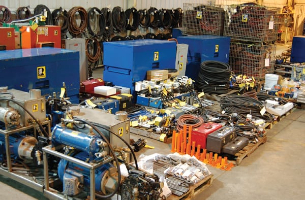 |
| 2. The right tools. A set of specialized tools is required for each crew working on a condenser retubing project. Courtesy: RetubeCo |
Removing Tubes
Tube removal involves performing three basic operations on each tube: cutting, pulling stubs and tubes, and traveling and chopping tubes. The time required to perform these tasks depends upon the material condition of the condenser, the quality of the crew, and the material handling and work spaces (Figure 3).
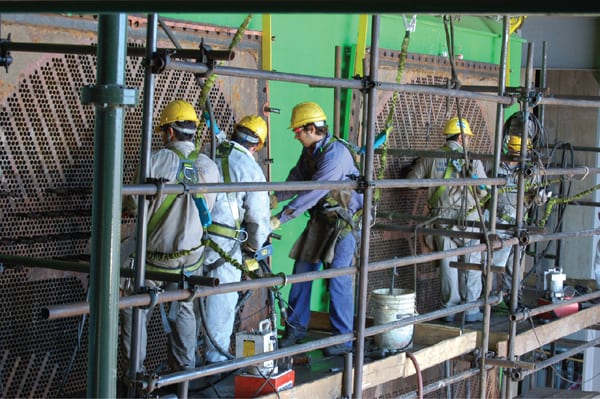 |
| 3. Cut! Condenser tubes are removed from the tube sheet after cutting off the tube at the other end of the condenser. The tubesheet is then prepped for the new tubes. Courtesy: RetubeCo |
As soon as access is gained to the back waterboxes and tubesheets, tube plugs are removed with suitable tools and work techniques. Although fiber, plastic, and rubber plugs are readily removed, solid tapered and ring and pin brass or steel plugs can be difficult to remove. Additionally, where one-piece metal plugs have been used, there is more potential for damaged holes and cracked ligaments. Tube holes having these types of plugs should be marked for increased quality control inspection.
Cutting Tubes. When the plugs have been removed, internal tube cutters are used to individually sever the tubes ½ to 1 inch beyond the inside face of the back tubesheet. The standard cutting rate is 250 to 350 tubes per hour per cutter. This work at the back end of the condenser can be performed while the covers or waterboxes are being removed at the front of the condenser and equipment is being set up to pull, travel, and chop the tubes.
Pulling Stubs and Tubes. When all the tubes have been cut, the stubs remaining in the back tube sheets can be removed with a collet-type tube puller as fill-in work. A sprinkler system is usually set up in the steam space to control dust and lubricate the tubes to facilitate their removal from the condenser. Tubes are usually removed starting from the bottom of the condenser and working up. Collet-type hydraulic tube pullers are used to individually grip tubes internally in the expanded area within the tubesheet, break free the tube-to-tubesheet joint, and pull the tube out 4 to 6 inches. Recall that the opposite ends of the tubes were cut earlier. If those tubes were not cut earlier, they would likely stretch or break when pulled at the front tubesheet. The tube puller is powered by a small portable hydraulic pump that can exert up to 11 tons of pulling force.
Traveling and Chopping Tubes. The tube traveler operates in conjunction with the tube puller. The traveler has a pair of toothed rolls that flatten the tube as it “travels” out of the condenser at a variable speed of up to 200 feet per minute. When the traveled tube is free of the tubesheet, it is drawn into a self-feeding chopper that chops it into 4- to 6-inch lengths and drops the pieces into a scrap container or palletized super sack. One chopper will process around two tons of tubing per hour—a truckload per shift. A large condenser can contain more than a million pounds of tubes.
Tubesheet and Support Plate Hole Preparation
Hole preparation requires cleaning and brushing, serrating (cutting grooves) where necessary, sizing, and inspecting each of the tubesheet and support plate holes.
The goal for cleaning support plate holes is to remove scale and return the hole size to design tolerances, typically 0.015 inch over nominal tube outside diameter per Heat Exchange Institute standards. Special carbide ball burrs driven by 1-horsepower pneumatic drill motors efficiently perform this operation. The ball burrs are made to ±0.002-inch diameter, with a left hand cut and right hand helix (which doesn’t pull into the cut), and are designed to not remove metal. A single pass with the burr lasting a second or two brings the hole back into tolerance. This operation must be carefully monitored by checking holes with pin gauges and checking the burrs for excessive wear with ring gauges. With several hundred thousand support plate holes and tens of thousands of tubes, proper and efficient preparation is critical to efficient tube sticking.
Next, tubesheet hole preparation involves cleaning each hole with a stiff stainless steel wire double twist hole brush a 16th of an inch larger than the hole diameter. Holes are then inspected to confirm design specifications, with 1% measured and recorded as benchmark holes for use in tube expanding quality assurance. If specified, 8-point serrations can be cut into the tubesheet holes. These concentric serrations, cut concurrently to a depth of approximately 1/64 inch, significantly increase joint strength and enhance leak-tightness. The tube-expanding process extrudes tube material into the grooves and against the 16 groove edges. After serrating, holes require a second brushing and inspection. Both cleaning and serrating of tubesheet holes can be completed at a high cyclic rate with the right tools and with little or no schedule impact.
Tube Installation and Expanding
Tube installation and expanding involves sticking each tube into the condenser, setting the inlet end of the tube relative to the tubesheet outer face, expanding the tubes into the tubesheet, and, if required, trimming and flaring tube ends (Figure 4).
 |
| 4. Training time. Staff are trained and qualified in correct installation methods before starting a condenser overhaul. Courtesy: RetubeCo |
Tube Installation. Scaffolding should be erected from the tubesheets to extend the full length of the tubes and to be able to support several tube boxes. Scaffolding should be independent at each tubesheet and lowered in 5- or 6-foot increments as tubes are inserted from the top down. Tube guides are used to guide the tubes through the support plates. The number of crews required can vary, depending upon the number, size, and layout of tubesheets, the schedule, and available manpower. The crew size for this evolution is usually about one person for every 10 to 15 feet of tube length.
Tube Expanding. A tube joint strength test, or pull-out test, is performed to determine the optimal apparent wall reduction by correlating tube wall reduction and the torque required to achieve it with pull-out strength. For the test, tube specimens from actual tube production lots are expanded into a mock tubesheet at various torques. The specimens are then pushed out with a load cell–equipped hydraulic press, and the various joint strengths are then calculated from the apparent tube wall reduction.
The mock-up tubesheet used in the test can then be used at the site in training and qualifying personnel to properly expand tubes using the “known hole method.” This method utilizes benchmark holes of the same diameter, simplifying the calculations required to control the tube-expanding process. Prior to tube insertion, a three-ball-type bore gauge is used to locate and mark 1% of the tubesheet holes with a common diameter (the “known hole”). These holes are marked on the tubesheet and recorded on a tubesheet map. When the operator expands a tube in one of these known holes, the expanded tube ID is measured and the rolling motor is checked on a torque analyzer to verify and record that the proper values are being maintained.
Vibration Mitigation
Finally, it is important that a comprehensive vibration study be performed when uprating or changing tube materials in a condenser. Such a study will determine the need for and the type of tube staking required. Stakes can be installed mid-span between support plates in each tube pitch to effectively shorten the unsupported tube span and prevent mid-span collision of tubes. Various stake configurations are available to allow for a variety of tubesheet patterns.
— Ed Overmyer (edo@retubeco.com) is president of RetubeCo Inc.