While many CO2 removal technologies are being researched through laboratory and pilot-scale testing, an existing technology has a significant operating history at commercial-scale facilities, where it is collecting CO2 from multiple sources, including low-CO2 concentration flue gas (<3.1% by volume) with high oxygen concentrations (>13% by volume).
Technology for the removal of carbon dioxide (CO2) from flue gas streams has been around for quite some time. The technology was developed not to address the greenhouse gas effect but to provide an economic source of CO2 for use in enhanced oil recovery and industrial purposes, such as in the beverage industry.
In 1989, Fluor Corp. purchased the license for a CO2 capture technology from Dow Chemical. Through the years of process and technology improvements, Fluor Corp. has developed an advanced amine-based postcombustion CO2 capture technology called Econamine FG Plus (EFG+). The EFG+ technology is the first and the most widely applied process that has extensive proven operating experience in the removal of CO2 from high-oxygen-content flue gases such as those typically present in a coal-fired power facility. The solvent formulation is specially designed to recover CO2 from low-pressure, oxygen-containing streams such as boiler gas streams without rapid degradation due to the presence of oxygen.
The EFG+ process utilizes simple, reliable equipment that is well-known to the gas-treating industry (Figure 1). The technology does not require a custom-manufactured or expensive solvent. The main ingredient of the solvent is readily available and inexpensive and is produced by solvent manufacturers worldwide.
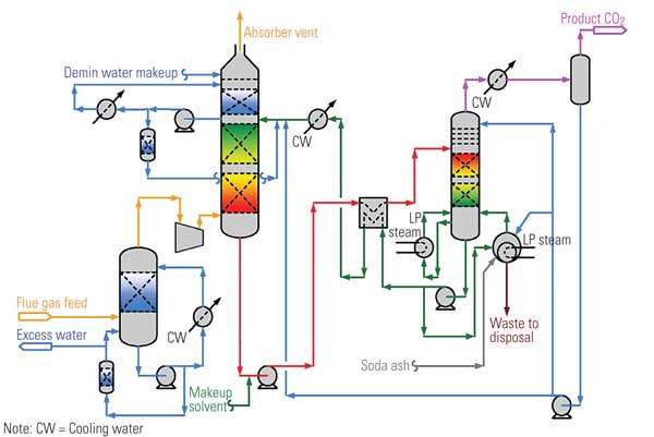
1. Go with the flow. The typical Econamine FG process uses simple, reliable equipment that is well-known to the gas-treating industry. Courtesy: Fluor Corp.
Commercial Plant Experience
In all, there are more than 25 licensed plants worldwide that employ the EFG+ technology — from steam-methane reformers to gas turbine power plants.
One of the most significant power applications of this CO2 removal system is at Florida Power & Light’s licensed plant at the Bellingham Energy Center in Bellingham, Mass, which captured 365 short tons per day of CO2 from the exhaust of the natural gas – fired power plant. The Bellingham plant is now owned by NextEra Energy Resources, a subsidiary of FPL Group Inc.
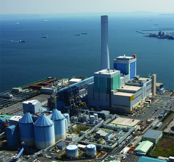
This EFG+ plant was designed and constructed by Fluor and maintained continuous operation from 1991 to 2005 (Figure 2). This facility is the only commercial-scale CO2 recovery unit in the world that has operated on gas turbine flue gas. In addition to its notably low CO2 concentration and high oxygen concentration, this flue gas stream is very pressure sensitive; a significant backpressure or pressure fluctuation in the flue gas cannot be tolerated.
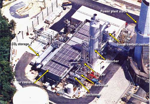
2. Standing the test of time. An aerial view of commercial-scale application of the EFG+ process capturing CO2 over 14 years of operation at the Florida Light & Power gas turbine power plant in Bellingham, Mass. Courtesy: Fluor Corp.
The experience gained from the design, construction, and 14 years of operation at the Bellingham facility is continually being used to further advance the EFG+ technology. Fluor has developed innovative strategies to prevent amine degradation and corrosion. No other technology supplier can match our long-term commercial operating experience with CO2 recovery from flue gas with a very high oxygen concentration, which translates into more reliable and cost-effective design and operation of future EFG+ plants.
Also of note, the EFG+ technology has been tested at greater than 90% removal, capturing 5 short tons per day of CO2 from coal flue gas with 40 parts per million of CO2. EFG+ also has been demonstrated on a plant that receives flue gas from a heavy fuel oil – fired power plant boiler. The flue gas from this source is much dirtier than flue gases from coal-fired power stations fitted with flue gas desulfurization (FGD) units and contains high levels of NOx, SOx, ash, and metals, including vanadium. At this plant, the pollutants and ash/metals were scrubbed to an insignificant level in a pretreatment unit located upstream of the EFG+ unit, making the source of the flue gas a nonissue for the solvent.
Enhancements to the CO2 Capture Technology
Fluor has developed an advanced simulator to account for mass transfer, heat transfer, and reaction kinetics. The simulator has been calibrated to performance test data from the Bellingham facility. This allows Fluor to test new configurations in order to further improve the EFG+ process. The technology has been continuously improved through solvent and flowsheet enhancements to lower both the energy consumption and solvent loss. These enhancements, along with advanced features, are incorporated into the current EFG+ designs.
Application at Coal-fired Power Plants
Even with the deployment of proven technologies with high-efficiency pollutant removal technologies, there are still residual quantities of sulfur dioxide (SO2), sulfuric acid (H2SO4), ammonia, particulates, and other trace constituents in the flue gas entering the carbon capture system. The CO2 absorption solvent will remove the majority of these pollutants. The bad news is that the presence of these pollutants in the flue gas increases the complexity and operating cost of the CO2 capture process — regardless of the technology.
Impurities in the flue gas — particularly SOx, nitrogen dioxide, hydrogen chloride, and hydrogen fluoride — will lead to the formation of heat-stable salt (HSS) in the amine systems. The HSS must be converted back into amine in a reclaiming process. Fluor has assessed that it is often more cost-effective to reduce HSS precursors before the flue gas encounters the solvent. The pretreatment step to remove HSS-forming precursors is a part Fluor’s process design strategy for coal-fired power plants (Figure 3).
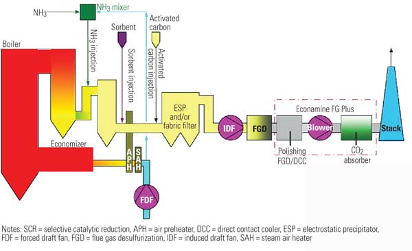
3. Snaring CO2 from flue gases. The application of EFG+ technology capturing CO2 at a coal-fired power plant. Courtesy: Fluor Corp.
In this example, a selective catalytic reduction system is used to control NOx. The next steps might be sorbent injection for control of sulfur trioxide gas and activated carbon injection for removing mercury from gas streams upstream of the particulate control device, which will usually consist of a dry electrostatic precipitator or a fabric filter or, in some cases, both.
Although Figure 3 shows the path for a wet FGD unit, many plants, especially those with low-sulfur fuel such as Powder River Basin coal, may use a dry FGD upstream of the particulate control device. Regardless of whether SO2 is removed by wet or dry FGD, the EFG+ system and most other postcombustion carbon capture technologies will be located downstream of the air quality control system. The flue gas will still have small quantities of particulates, SO2, ammonia, and other pollutant species that will need to be identified, quantified, and considered in the design of the CO2 capture unit.
The new equipment added in the flue gas path for carbon capture depicted in Figure 3 includes a polishing FGD or direct contact cooler (DCC) with scrubbing capability, a blower, and a CO2 absorber.
Increased control of SO2 may be accomplished by one or more of the following approaches:
-
Incorporate additional mass transfer with an existing or new FGD.
-
Add an additional separate polishing scrubber.
-
Include scrubbing capability in the DCC.
-
Change the reagent to enhance SO2 removal in the FGD.
Carbon Capture Ready
Provisions for the addition of postcombustion CO2 capture can vary from being aware of the requirements for the design to full integration of the power, steam, and cooling needs, as well as infrastructure for CO2 transportation. At a minimum, the analysis and early decisions concerning CO2 capture, with particular emphasis on the commercial EFG+ technology, should include in-depth analysis of the following topics.
Permitting. The facility permits and operations philosophy should give maximum operational flexibility to the CO2 capture system. The operational philosophy and design should allow flexibility in the event that sequestration wells, the buyer for the commercial grade CO2, or the enhanced oil recovery end user cannot accept CO2 for any reason.
CO2 capture should be permitted on a mass of CO2 per year rather than a percent removal basis. This would allow for upset conditions and periods when the CO2 compression and pipeline system is unavailable. In addition, it would potentially allow the capture system to be run during off-peak periods such as winter (for summer peak areas) or nighttime operation.
The emissions dispersion modeling must consider the lower gas volume and potentially cooler gas stream. The stack construction materials must be compatible with wet flue gas. Certain carbon capture processes may require reheat of the gases prior to the stack to ensure that the temperature is compatible with stack materials or to make sure that the gas buoyancy is sufficient for the requirements.
Consideration should be made for the use of potential waste streams from the CO2 capture process within the boiler and FGD systems’ water balance. These streams include condensed water from the DCC and chemical streams from the reclaimer. The water may be used as FGD makeup, for ash wetting, or for other purposes. The water could also be treated by integration into the base plant’s water treatment facilities.
Plant Arrangement. "Capture ready" has for many meant space allocation for future technology implementation. Large-scale CO2 capture and sequestration projects that are currently in development require multiple CO2 absorption trains that require large plot areas. Even for smaller CO2 capture retrofit applications, plot availability can play a vital role in the project’s feasibility. As a result, Fluor has focused on strategies to minimize the footprints of EFG+ plants, including large-diameter absorber design, plate and frame exchanger train minimization, and reboiler shell count minimization.
Space allocation and/or provisions for the CO2 capture system must also include consideration of booster fans, absorber columns, DCC, gas separation units, cooling equipment, CO2 compression/storage equipment, reclaimer, building infrastructure expansions, reagent tanks/unloading, pipe/ductwork corridors, and maintenance access.
Power Plant Integration. Consideration should be made to integrate the steam requirements into the boiler, turbine, feedwater, and condenser circuits to limit the impact on the power production of the generator and fully optimize the entire power generation/carbon capture system. Because the CO2 capture system uses significant quantities of steam and power, the steam and electrical cycles should be thoroughly evaluated to provide the most energy efficient solution. If CO2 capture is continuous, one option is to use a smaller turbine and size the boiler to produce both high-energy steam for the turbine and low-energy steam for the CO2 capture system. If the CO2 system can be turned off — for example, to maximize power during peak load times — then the turbine should be sized to match the boiler production.
For new coal-fired power plants, integration of the EFG+ technology into the plant’s cycle heat balance needs to be evaluated based on site-specific requirements and conditions. Various alternatives may be studied to determine the best solution for a particular application based on project economic factors, planned CO2 capture efficiency, planned CO2 capture capacity factor (percentage of time operating), and site ambient conditions.
Fluor has studied various cycle heat balance optimization approaches for multiple power plant sizes. For illustrative purposes, the approach outlined below is based on a typical 850-MWe coal-fired power plant (Figure 4).
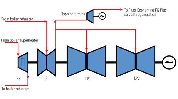
4. Easy integration. Multiple options are available to power plant design engineers for cost-effective integration of the EFG+ process into the plant steam cycle. The approach illustrated here uses steam extraction from the intermediate turbine exhaust to supply solvent regeneration heat requirements. Courtesy: Fluor Corp.
For this case, the steam demand for regeneration of the solvent could be approximately one-third of the steam flow to the low-pressure (LP) turbine. Optimally, the steam would be extracted from the steam cycle at the lowest potential energy point that still provides sufficient heat energy to regenerate the solvent. Doing so ensures efficient use of the steam energy in power production prior to providing steam to the carbon capture system. This can be accomplished by extracting steam at the intermediate pressure (IP) to LP "crossover" portion of the steam cycle. Impacts to the IP turbine must be accounted for in blading design due to the various operating cases that may be generated by the CO2 capture operating load and power plant operating load.
If the steam pressure requirements for solvent regeneration are lower than the crossover pressure (as they would be for the typical 850-MW cycle described above), a smaller topping turbine may be used downstream of the cycle extraction to recover some of the steam energy that would otherwise be lost through control valve throttling, as shown in Figure 4.
As discussed above, other steam cycle design alternatives may be employed to meet the carbon capture system’s energy needs. In addition to the steam cycle impacts, electrical demand impacts on the facility’s power supply gear, water system, and control system architecture must be addressed.
The Future Is Now
Integrating carbon capture into a new or existing power plant has major impacts on the facility that require careful analysis and decision-making, beyond simply adding space or capacity for electrical power and steam. Wise decisions can reduce the impact on the plant and improve the economics of power production.
The EFG+ technology is a proven, cost-effective process for removing CO2 from low-pressure, oxygen-containing flue gas streams. The performance of the process has been successfully demonstrated on a commercial scale over the past 20 years, and Fluor continues to build on these years of technology development and experience.
Fluor and E.ON Energie AG (E.ON) have formed a strategic partnership for the development of a retrofitted pilot plant using the commercially proven EFG+ carbon capture technology. The pilot plant will begin operation in 2010 at E.ON’s coal-fired power plant in Wilhelmshaven, Germany. The primary focus of this partnership is to enhance the technology and to demonstrate its application to safely separate carbon from the flue gas of a coal-fired power plant by processing 17,000 normal cubic meters per hour of power plant flue gas and recovering 90% of the CO2 contained in that gas.
—Dennis W. Johnson (dennis.johnson@fluor.com) is the senior director of process specialty engineering at Fluor Power. Dr. Satish Reddy (satish.reddy@fluor.com) is the executive director of process specialty engineering at Fluor Enterprises Inc. James H. Brown, PE, PMP (james.brown@fluor.com) is the director of engineering of the solid fueled projects business line at Fluor Power.