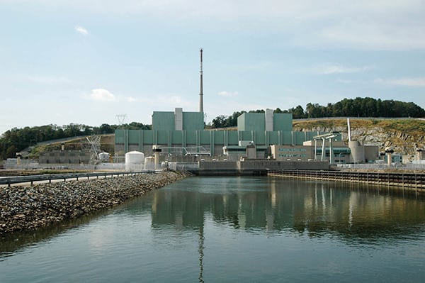
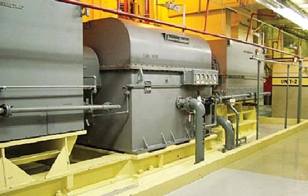
Controlling the power output of a boiling water reactor (BWR)—such as Exelon Nuclear’s Quad Cities Unit 1 or 2 (Figure 1)—requires changing the reactivity of the core by repositioning the control rods and controlling coolant flow through the core.
1. First in line. Exelon Nuclear’s Quad Cities Unit 1 will have its reactor recirculation flow control systems upgraded with electronic adjustable-speed drives in the spring of 2009. Courtesy: Exelon Nuclear
For a given control rod line, increasing flow causes steam bubbles (“voids”) to be reduced, which increases the amount of liquid water in the core. With more liquid available, more neutrons are slowed down (moderated) to a speed suitable for splitting fissile fuel. More fission means more thermal power. Decreasing flow through the core has the opposite effect on power output.
When a BWR is operating on the so-called “100% rod line,” its power output can be varied from roughly 70% to 100% of maximum rating by varying the speed of the recirculation pumps or by throttling a flow control valve.
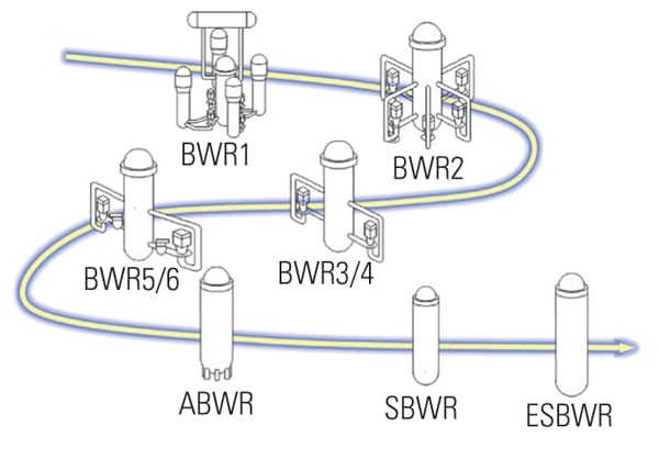
The BWRs of interest in the U.S.—the BWR-3 through -6 designs—have two recirculation loops (Figure 2). Each loop has one pump whose flow is controlled by either of two systems: a motor-generator (M-G) set that uses large, medium-voltage induction motors to drive the recirc pumps or a flow-control valve design. Either system provides controllable recirculation flow through the reactor core.
2. Gone fission. A simplified diagram of a typical BWR plant and the recirculation loops that control the thermal output of the reactor. The pumps’ flow controls were the subject of an extensive upgrade option analysis by Exelon Nuclear. Source: Exelon Nuclear
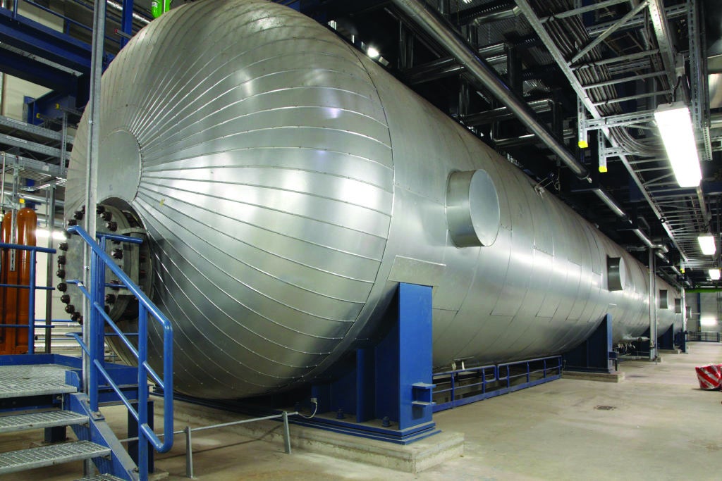
The earlier (BWR-3 and BWR-4) designs use M-G sets. This control design allows variable adjustment of motor voltage and frequency and uses a voltage regulator to keep their ratio constant. The motor, operating at medium voltage, drives the generator through a fluid coupling that acts like a clutch. The speed and output of the generator rise and fall as the volume of fluid in the coupling is varied by changing the position of a scoop tube, or weir. As the generator’s output increases or decreases, the speed of the recirc pump follows suit. Figure 3 shows an M-G set from Quad Cities Nuclear Generating Station in Illinois.
3. Long in the tooth. A typical M-G set for controlling a BWR-3 recirculation pump. Courtesy: Exelon Nuclear
The flow-control valve design is standard at the later BWR-5 and BWR-6 plants, which also use an M-G set to power the pump at low frequency (15 Hz) and low speed (25% of maximum). A direct connection of the pump motor to the medium-voltage source provides for a faster speed at line frequency (60 Hz). A modulating flow-control valve in the loop adjusts the recirculation flow as required.
High time to upgrade
Both control designs have exhibited problems that have resulted in excessive maintenance costs, generating inefficiencies, and enough loss of control to warrant a unit de-rate. Making matters worse, spare parts have become scarce, which has resulted in extended outages for unplanned repairs.
Among the parts of both designs that have become troublesome are flywheels, scoop tubes, voltage regulators, and scoop tube positioners. Backups for those components (if available), as well as large inventories of M-G lubricating oils, fluid for the coupling, hydraulic fluid for control valve power units and shuttle valves, and generator brushes must be kept on the shelf. Spare parts for auxiliary lube oil, cooling water, and ventilating systems also must be kept on hand.
Within the reactor building, the primary piping and pump pressure boundaries are critical to safety, but the power and instrumentation portions of the water recirculation systems are not. However, their fault tolerance and obsolete components have caused reliability problems at several BWRs. Specifically, the old electromechanical analog technology used to control the speed of recirc pumps is vulnerable to hysteresis, sensitive to temperature, and prone to “hunting” due to mechanical dead bands and a limited range of output frequencies. Any of these conditions can reduce a unit’s capacity factor, a key measure of its performance.
Cheaper by the dozen
Solid-state static power converters—also known as variable-frequency drives or adjustable-speed drives (ASDs)—represent the state-of-the-art technology suitable for replacing the M-G sets. Like M-Gs, ASDs generate a signal whose voltage and frequency are continuously adjustable at a constant ratio, but they do so with no moving parts (with the exception of small pumps and fans for a closed-loop cooling water system). The beauty of this recirc pump upgrade option is that the recirc pumps, motors, and motor cables should not require modification.
Exelon Nuclear’s design philosophy is “Design Once, Install Many.” Accordingly, a key goal of the process of choosing a replacement for the M-Gs was to select an ASD system design and product compatible with similar medium-voltage applications across its fleet. Doing so would minimize costs by allowing the sharing of spare parts and O&M experience. Across Exelon Nuclear’s fleet of 12 BWRs (see table), the design voltages of existing M-G sets, rated from 5,770 hp to 8,900 hp, range from 4,160V to 6,900V.
Exelon Nuclear’s U.S. BWR fleet. Source: Exelon Nuclear
Although the recirc pump speed control system is not critical to safety, it is essential to production and therefore requires high reliability and minimal points of single failure. Exelon Nuclear evaluated three basic system design concepts, each of which assumed that a single-train ASD will have either a very low probability of failure or inherent redundancy:
- Two ASDs with redundant power trains, one for each of the two recirculation pumps (Figure 4a).
- Two primary ASDs with a swing drive that can pick up the load from one of the primary units in the event of a trip (Figure 4b).
- Two single-train ASDs (Figure 4c).
4. Choose your weapon. Three conceptual options for upgrading recirc pumps with adjustable-speed drives. Source: Exelon Nuclear
The basis of the redundant power train concept is that the two parallel power cell trains would share the recirculation pump’s electrical load. If a power cell in one of the trains were to fail, the remaining train would pick up the full load, satisfying the “minimal points of single failure” criterion. However, such a system was ruled out because it would have been unique in the U.S. nuclear industry. Note also from Figure 4a that eight large circuit breakers or vacuum contactors would have to be added as part of the design, and they would consume a lot of floor space. The design has one upside: It would allow on-line maintenance of the power cells.
The swing-drive concept would require use of a complicated scheme to “swap over” to the swing ASD (Figure 4b, center) the pump driven by a failed primary ASD while it was coasting down. The speed lost by the affected pump would depend on how long it took to make the swap. During the design evaluations, it was suggested that it would take between 200 msec and 3 seconds, but that range was never verified by testing.
Like redundant power trains, the swing-drive concept had never been implemented in a nuclear power plant. It had the same upside—allowing on-line power cell maintenance—and a similar downside: A lot of plant floor space or a large power distribution center would be required for the installation of three drives. However, the swing-drive configuration also was ruled out for a very good reason: Failure of any of the eight breakers in the system (six new and two existing) would cause the swap to fail.
The dual single-train ASD system (Figure 4c), using solid-state power trains with a statistically low failure frequency, would be more reliable than the existing M-G set design. Its big downside is not allowing on-line power cell maintenance. However, such maintenance should not be needed if the cell’s mean time to recovery is reasonably short (one shift or less).
Even though the twin ASDs would be more efficient and require less preventive maintenance and consumables than an M-G set, engineers decided that the basic design was insufficiently robust. They then addressed that shortcoming by insisting that the drives have a cell bypass feature to maintain their voltage output even if one or two power cells were to fail.
And the winner is . . .
The design concept shown in Figure 4c was the final choice for its simplicity, relative compactness, and high reliability. The ASD selected was the Robicon Perfect Harmony, Model WCIII, medium-voltage (2,300V to 14,400V) drive from Siemens Automation and Drives (www.siemens.com/medium -voltage-converter). As specified, the drive’s patented power cell bypass feature allows full operation of the recirculation pump with one or two power cells failed and bypassed. The WCIII nomenclature signifies that the drive (Figure 5) is a water-cooled, third-generation unit.
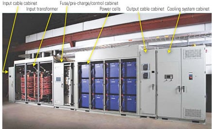
5. Compact recirc pump drive. The water-cooled Robicon Perfect Harmony medium-voltage adjustable-speed drive was chosen primarily for the high system reliability afforded by its cell bypass feature. The third-generation design integrates the NxG II control system, also from Siemens Automation and Drives. Source: Exelon Nuclear
The Perfect Harmony ASD is a modular unit with two inverters. One uses pulse-width modulation, a diode rectifier, and a DC filter inductor/link capacitor; the other is a conventional, multistep voltage source inverter. Insulated-gate bipolar transistors are the active components of inverter circuits.
Unlike other ASDs, this one does not require the use of input and output isolation transformers, input or output harmonic filters, dV/dt filters, isolation breakers, or power factor compensation. That’s because its integral transformer with phase-shifted secondaries provides 18-pulse or better input harmonic cancellation with an expected power factor of 0.97 under any operating conditions. One can expect the Robicon Perfect Harmony drive to be available between 99.99% and 99.999% of the time.
The cell bypass feature enables the ASD to provide full power to the pump in the event of a power cell failure. When the control system—a Model NxG II, also from Siemens Automation and Drives—detects such a failure, it calculates the magnitude of the phase shift and voltage adjustment needed to keep the ASD’s reduced output balanced. The bypass circuit’s salient feature is its overrating of the nominal design output voltage, which maintains the reduced but balanced output greater than the voltage required for 100% motor speed. The motor current is momentarily removed during the calculation and adjustment process. By contrast, the motor speed is reduced by 10% but reapplied with the new balanced output within about 250 milliseconds.
This ASD has been used widely and successfully in the petrochemicals industry. One Perfect Harmony unit at a chemical plant operated continuously for five years without ever having to be derated. As mentioned earlier, although the system of two single-train ASDs does not allow on-line maintenance of power cells, the need for it should not be critical because one power cell failure will not result in a tripped or derated ASD.
Designed for reliability
Each ASD in the final system design has redundant commutator-inverter NxG II processors. Either processor can act as the primary or secondary controller because both can be configured with the ASD parameters, system control algorithms, and the controller “swapover” scheme.
Redundant supervisory controllers—Siemens S7-400H units—will interface the drive system to the existing reactor recirculation flow control system (RRCS) at the plant to be upgraded. The controllers are fault-tolerant and self-diagnostic. Redundant power sources are required for all the control systems and control subsystems. Figure 6 illustrates a typical dual Profibus, fault-tolerant control system architecture with redundant remote I/O suitable for such an application. An alternate design would provide dual network communications using the existing RRCS. A third option would combine remote I/O and network communications. It’s worth noting that these redundant control systems have no points of single failure.

6. Control connections. The ASD control architecture for a remote I/O system design with network communications. Source: Exelon Nuclear
Each ASD has a self-contained, closed-loop cooling water system. Redundant pumps and instrumentation make these systems highly reliable. Other than the common cooling water piping, which has a very low probability of failure, the cooling system is single-point failure-proof.
Other design considerations
Besides reliability and the ability to adjust motor control voltage and frequency, the major considerations for upgrading the recirc pump drive system at a particular BWR include available floor space, floor loading, cable and raceway quantities, the ease of interfacing with existing plant systems, heat sink design parameters, and loading effects on ventilation systems and fire detection/suppression systems. If plant real estate is at a premium, a dedicated ASD outbuilding may be a viable option. The use of such a structure would minimize construction within an operating plant and, if it were strategically placed, could shorten needed cables and raceways.
Replacing existing M-G sets and their ancillary equipment presents several challenges. If the outage scheduled to perform the work is long enough, and cranes and personnel do not compete for laydown space, the old equipment can be removed and the new ASDs can be placed in the same general area. This would likely minimize needed quantities of new cable and raceway. It may be possible to do some of the installation work (but not tie-in or commissioning) before the outage begins.
Special analyses required
For an ASD upgrade to a nuclear power plant, some special analyses are required to satisfy the U.S. Nuclear Regulatory Commission (NRC). For example, the plant owner must perform a reanalysis of licensed events to determine the effect of changing the motive sources of the recirculation pump motors from M-G sets to ASDs. The analysis must show that the effects are bounded by existing analyses; if they are not, the planned modification must be submitted to the NRC for approval prior to implementation. Exelon Nuclear anticipates that the reanalyses will show that the retrofitted systems are indeed bounded by existing analyses.
Following are some of the specific impacts of an ASD upgrade that would require an analysis/evaluation:
- Unlike M-G sets, ASDs do not provide electrical inertia for pump/motor coastdown. So coastdowns will be quicker for some trip scenarios.
- ASDs are not mechanically limited by the 25%/second fluid coupler, as M-G sets are. The effect of this freedom on transient flow increases must be considered.
- Because ASDs can deliver higher-frequency voltages than M-G sets do, overfrequency situations are a possibility (M-G sets use a mechanical stop to avoid them). Although software is typically used to limit ASD output frequencies, external frequency-sensing relays must be ready to step in if the program fails.
- An ASD can apply braking action to a recirc pump motor; an M-G set cannot. If an ASD malfunction triggers this braking action, its negative effects should be limited to a pump trip and coastdown, or a pump seizure.
- ASDs have motor reversing capabilities. Even the failure of an ASD that is not enabled may cause a motor reversal. Accordingly, an ASD upgrade must include the installation of motor management relays (to trip the motors upon a phase reversal) and the implementation of other motor protection parameters.
The M-G sets at earlier, BWR-3 and -4 plants operate over the same continuous frequency range (and, hence, over the same speed range) as the ASDs. However, the flow-control valves at later, BWR-5 and -6 plants operate (other than during transients) at only two speeds: 25% and 100%. Upgrading to ASDs will enable the recirc pump motor drives of those reactors to operate over the same continuous range as their predecessors.
This change requires performing hydraulic analyses of recirculation flow sensing line vibrations and of dead-leg pressure oscillations from side-branch harmonics (see "Accurately measure the dynamic response of pressure instruments" in this issue for more information on pressure-sensing issues) because the sensing lines in question are inside the reactor. Modifications to sensing line clamps/supports or dead legs may be required as well. The analyses and any mods should be done at least one outage prior to the outage for installing the ASD upgrade. Field surveys can provide valuable “as-built” input data for these analyses; if possible, they should be done at least two outages prior to the upgrade outage.
For fundamental guidance on the operation, selection, and application of medium-voltage (2,400V to 13,800V) ASDs, refer to IEEE Standard 958-2003. Harmonics analysis and testing should be done in accordance with ANSI/IEEE 519: Recommended Practices and Requirements for Harmonic Control in Electrical Power Systems.
Finally, an ASD upgrade should be accompanied by a torsional analysis, to identify any harmful torques and vibrations on the shafts of all motors and drive equipment at all speeds under normal and abnormal conditions. This analysis usually is performed using a computer model containing critical speed points, natural frequencies, mode shapes, steady-state operating torques over the entire speed range, oscillating component harmonics, transient torques, and stresses during acceleration and deceleration of the drive through its mechanical resonance frequency. Among the corrective actions that can alleviate or eliminate torsional problems are installing energy-absorbing couplings or oil lift bearings, and machining shafts to reduce their stress levels.
Have other reactors upgraded to ASDs?
The answer is yes. That’s important, because plants considering the same modification can benefit from lessons learned by the pioneers and from their operating and maintenance experience.
Specifically, Energy Northwest’s 1,157-MW Columbia Generating Station retrofitted load-commutated inverter-type ASDs for its recirculation pumps in the mid-1990s. Tennessee Valley Authority’s (TVA’s) Browns Ferry Nuclear (BFN) Plant also installed three Perfect Harmony Model WCII units (the predecessor of the WCIII) between 2003 and 2005 and has since accumulated more than eight years of operating experience on them. Siemens made about 50 changes to the WCII based on lessons learned from the BFN installation by a TVA users’ group. Finally, Southern Nuclear’s Plant Hatch and Progress Energy’s Brunswick Plant have purchased the Perfect Harmony WCIII drives and have begun designing them into systems scheduled for installation in the spring of 2009.
Examine your business case
Because the new ASDs are more efficient than M-G sets, they should reduce house loads. This reduction for Quad Cities Unit 1 is anticipated to be 2.5 MW. Although the expected improvement in system reliability from the upgrade is harder to quantify, it should be significant, as should the reduction in maintenance costs. Fuel savings also should be realized because, unlike M-G sets, ASDs can deliver full flow at the end of the nuclear fuel cycle.
Exelon Nuclear has concluded that a project to upgrade from M-G sets or flow-control valves to ASDs will deliver a positive net present value and a very attractive internal rate of return, with typical business case assumptions. How good would the economics be at your BWR? You’ll have to do your own analyses that take into account the particulars of your plant. But at Exelon Nuclear, the results of in-depth studies convinced corporate management that adding ASDs at Quad Cities in the spring of 2009, and at the remainder of its BWR fleet in the future, is an excellent idea.
—James W. Morgan (james.morgan@exeloncorp.com) is a principal engineer for instrumentation and control with ILD Inc. (www.ildpower.com). On assignment to Exelon Nuclear’s corporate engineering department, he is the lead engineer responsible for Exelon’s fleetwide upgrade of reactor recirculation pump flow control systems.