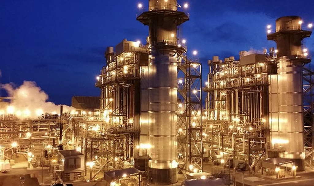
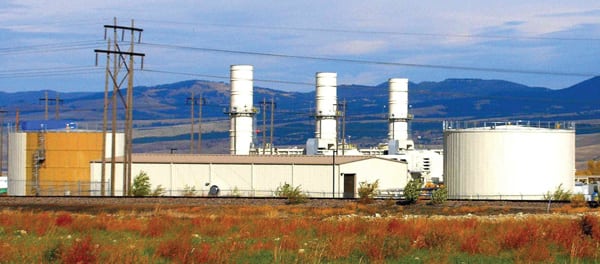
The Panoche Energy Center is a 400-MW simple-cycle power plant using four of General Electric’s GE LMS100s with fast-start capability. Dispatched by Pacific Gas & Electric to meet regional power and grid stabilization needs, the project entered commercial service two months earlier than planned. Panoche is the largest LMS100 peaking facility in the U.S.
Panoche Energy Center (PEC) got its start in December 2004 when the California Public Utilities Commission authorized Pacific Gas & Electric (PG&E) to “plan for and procure the resources necessary to provide reliable service to their customer loads for the planning period 2005 through 2014.” PG&E’s resource planners pored over their computer models and determined that 1,200 MW of new peaking generation were required in 2008 and another 1,000 MW of new peaking and dispatchable generation would be required in 2010. The company began the process of acquiring that new peaking and dispatchable generation, located in a designated area of its service territory, with a competitively bid request for offers (RFO) issued on March 18, 2005.
APEX Power Group LLC was one of several successful bidders on the RFO. It signed a contract for 400 MW of dispatchable gas-fired generation in April 2006.
Project Conditions
The 20-year power purchase agreement (PPA) required the PEC, located in western Fresno County about 50 miles from Fresno, to be in commercial operation by August 1, 2009, to avoid delay-related damage payments. Other terms of the PPA shaped the possible generation options for the project, but PEC selected four of General Electric’s LMS100 simple-cycle combustion turbines (CTs) as the best technology. Other key PPA terms and conditions included those detailed below.
A Compact Project Site. The PEC is located on a 12.8-acre site leased by the developer within a 128-acre parcel owned by PG&E that is adjacent to the Panoche Substation. This site also provided other advantages to the developer: Only 2,400 feet of natural gas pipe were required to provide fuel to the plant, and the Panoche Substation is located only 300 feet from the plant site. However, gas pressure at the project site varies seasonally, from 400 psig to 1,000 psig, so gas compression is required to meet the CTs’ required 950 psig inlet pressure.
Fast Response. The 100-MW LMS100 is able to ramp from a cold start to full load in 9.5 minutes, according to plant test data. With four CTs, PG&E can easily dispatch convenient 100-MW blocks of load into the critical Path 15 corridor. By locating the plant adjacent to an existing switchyard, PG&E avoided substantial substation upgrade costs to keep project cost as low as possible.
The PPA requires PEC, as an intermediate-load and peaking facility, to operate up to 5,000 hours a year at a service factor of 57% (the percentage of time that a unit is operating regardless of load) and a projected equivalent availability factor of between 95% and 99% (the weighted average of the percentage of energy production achievable). The PPA also allows PG&E the option of up to 365 start-ups and shutdowns each year.
High Efficiency. Each LMS100 operates at an estimated 7,815 Btu/kWh heat rate at full load at 59F and 60% relative humidity while producing 103 MW at the generator terminals. GE added the LMS100 to its stable of gas turbine generators late in 2003 to address growing demand for efficient, mid-range (80 MW to 160 MW) peaking capacity. GE answered that need by carefully mixing and matching the best parts of its aeroderivative and industrial machines and designing the rest.
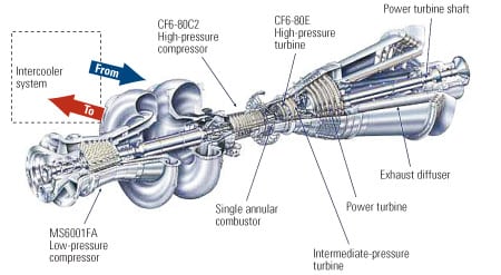
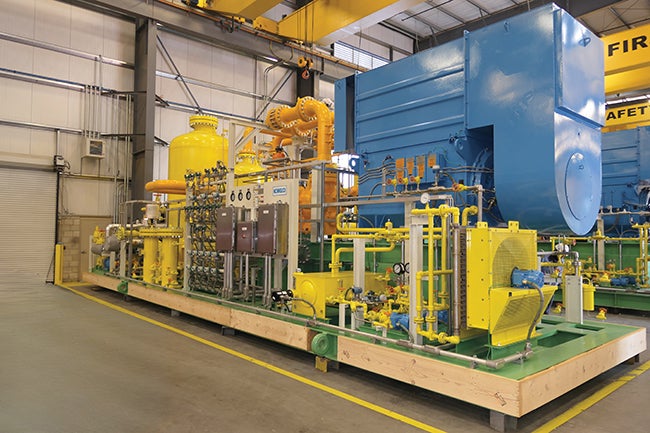
One of the keys to the excellent part-load efficiency of the LMS100 is its intercooler. It increases the turbine’s efficiency by precooling the air supply for the high-pressure compressor, thereby decreasing its power needs (Figure 1).
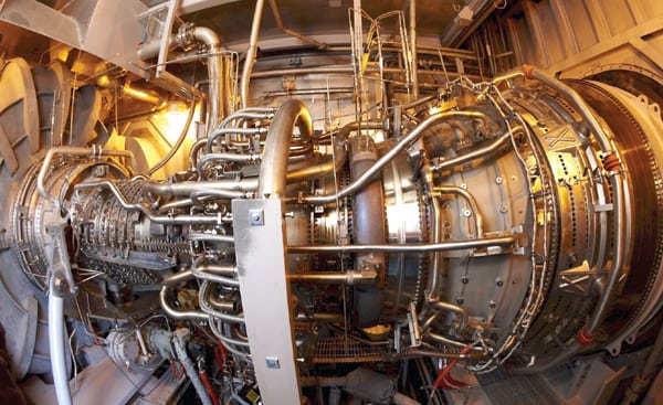 |
| 1. All in the family. The LMS100 low-pressure compressor has exactly the same parts as the first six sections of the heavy-duty low-pressure compressor in the MS6001FA power generation workhorse. But the technologies used in its supercore—the high-pressure compressor, combustor, and high-pressure turbine shown in this photo—first proved themselves in GE’s LM aeroderivative products, which are descended from the CF6-class aircraft engine. Also, the engine’s two-stage intermediate-pressure turbine and five-stage power turbine are based on the latest GE aeroderivative technology, and the latter was designed specifically for the LMS100. The external intercooler placed between the high-pressure and low-pressure compressor helps improve part-load efficiency: Even at 50% turndown, the LMS100 is nearly 40% efficient. Courtesy: Kiewit |
Minimal Water Use. Using fin-fan coolers for the CTs’ intercooler added a performance penalty that reduced turbine output below the 400 MW net contract requirement, especially during the design 114F summer day when the entire output of the plant is critically required. The solution was to incorporate a common evaporative cooling tower for the CT intercooler cooling system. This approach enabled PEC to achieve higher electrical output and a lower heat rate during peak, high-ambient-temperature conditions.
However, using potable well water for makeup to the single, four-cell evaporative cooling tower was unacceptable, so water wells were drilled into a brackish water aquifer. An ultrafiltration system, two-pass reverse osmosis skid, and a mixed bed demineralizer that is regenerated offsite by a contractor treats the brackish makeup water. The evaporative inlet coolers are used whenever the ambient temperature is higher than 60F, as the coolers are effective given the usual low ambient humidity. High volumes of cooling tower makeup (1,250 gpm) are required because only three cycles of concentration are possible given the high silica level in the brackish water supply. Wastewater from the plant is disposed of using a deep well injection system.
Environmentally Responsible. Even though the CTs only operate in simple-cycle mode, they must meet regional air emissions requirements, specifically: NOx ≤2.5 ppmvd, CO ≤6.0 ppmvd, and ammonia slip ≤10.0 ppmvd—all corrected to 15% O2—plus PM10 ≤10 lb/hr, all measured at full load. To meet these requirements, PEC selected a combination of CT water injection and exhaust gas catalysts to control air emissions. The SCR uses a 19% aqueous ammonia injection to remove NOx from the exhaust gas. An oxidizing catalyst reduces the CO in the exhaust to permit levels.
Fast-Track Schedule
Because the project exceeds 50 MW, siting jurisdiction fell to the California Energy Commission (CEC). The required Application for Certification was filed by PEC in August 2006, only four months after the PPA was signed with PG&E. The following month, an order was placed with GE to purchase the four LMS100 CTs and associated equipment, including the SCR system. On July 7 of the following year, PEC signed a full-wrap engineering-procurement-construction (EPC) contract for the engineering and construction of PEC by Kiewit Power Engineers and Kiewit Power Constructors. Power Plant Management Services was retained as the PEC asset manager. The Wood Group is the onsite operation and maintenance (O&M) contractor. A dozen Wood Group O&M technicians and supervisions keep the plant running reliably.
The CEC’s final order approving the project—the final permit required before financing of the project could be finalized—was issued in December 2007. Financial closing on the project occurred in January 2008, 21 months after the PPA was signed.
Recovering from Delayed Deliveries
Delivery of equipment posed exceptional challenges during construction, especially with the first of the four CT main units. Major equipment (many loads weighed up to 200 tons) was slated to travel by highway from the manufacturing plant near Houston, Texas, with over-the-road trucks as long as a football field. Due to changing requirements from several states’ transportation departments for permitted loads, haul routes and shipping restrictions delayed the first unit’s planned transport schedule. The first CT was 76 days in transit.
Delays in equipment delivery were particularly critical because the project was planned to be built from the inside out on a very compact job site. The Kiewit Power and GE team immediately stepped up to the challenge and rescheduled construction and engineering resources by modifying balance-of-plant construction sequencing. The team also worked closely with GE to overcome shipping restrictions on overland heavy haul issues and expedited unit deliveries via barge shipments to a port closer to the facility site. A dedicated barge that was able to dock in Stockton significantly reduced time on the road and proved to be a much more schedule-efficient solution: The last CT was only 30 days in transit.
Throughout the project, the Kiewit team was able to successfully meet or beat their project milestone dates—a marked difference from the many other developers and contractors awarded projects under the same RFO. The Kiewit team was the exception, bringing the PEC project to completion ahead of schedule. Construction began the month after financial closing (February 12, 2008) and the CT foundations were quickly completed. The four CTs and associated equipment were set from October through December of 2008. Commercial operation of PEC was achieved on June 1, 2009, two months ahead of the July 31, 2009, contractual deadline required by the PPA. All personnel safety goals were also met; there was only a single recordable injury during construction.
Operation of PEC has been exceptional since the plant began commercial service. In December 2009, all four units were dispatched by PG&E for 364.2 hours, experienced 83 starts, and sold 24,618 MWh. By the conclusion of 2009, PEC had operated for 2,122 fired-hours (the sum of each combustion turbine’s fired-hours) with a start reliability of 99.8%. Through the first six months of 2010, PEC has operated for 1,415.1 fired-hours with a start reliability of 99.6%.
— Dr. Robert Peltier, PE is POWER’s editor-in-chief.