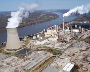
The combustion of coal in power generation facilities produces solid waste, such as bottom and fly ash, and flue gas that is emitted to the atmosphere. Many plants are required to remove SOx emissions from the flue gas using flue gas desulfurization (FGD) systems. The three leading FGD technologies used in the U.S. are wet scrubbing (85% of the installations), dry scrubbing (12%), and dry sorbent injection (3%). Wet scrubbers typically remove more than 90% of the SOx, compared to dry scrubbers, which remove 80%. This article presents state-of-the-art technologies for treating the wastewater that is generated by wet FGD systems.
Wet FGD Basics
Wet FGD technologies have in common a slurry reactor section and a solids dewatering section. Various types of absorbers have been used, including packed and tray towers, venturi scrubbers, and spray scrubbers in the reactor section. The absorbers neutralize the acidic gasses with an alkaline slurry of lime, sodium hydroxide, or limestone. For a number of economic reasons, newer scrubbers tend to use limestone slurry.
When limestone reacts with SOx in the reducing conditions of the absorber, SO 2 (the major component of SOx) is converted into sulfite, and a slurry rich in calcium sulfite is produced. Earlier FGD systems (referred to as natural oxidation or inhibited oxidation systems) produced a calcium sulfite by-product. Newer FGD systems employ an oxidation reactor in which the calcium sulfite slurry is converted to calcium sulfate (gypsum); these are referred to as limestone forced oxidation (LSFO) FGD systems.
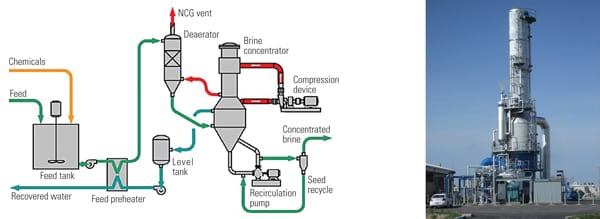
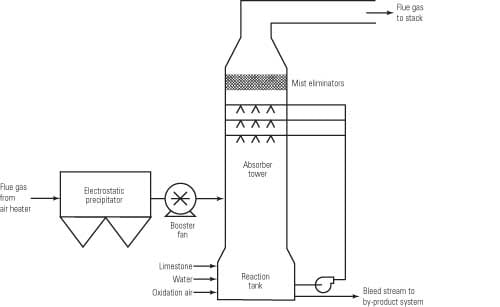
Typical modern LSFO FGD systems use either a spray tower absorber with an integral oxidation reactor in the base (Figure 1) or a jet bubbler system. In each the gas is absorbed in a limestone slurry under anoxic conditions; the slurry then passes to an aerobic reactor or reaction zone, where sulfite is converted to sulfate, and gypsum precipitates. Hydraulic detention time in the oxidation reactor is about 20 minutes.
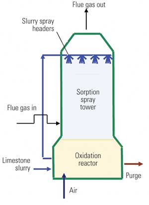
1. Spray column limestone forced oxidation (LSFO) FGD system. In an LSFO scrubber slurry passes to a reactor, where air is added to force oxidation of sulfite to sulfate. This oxidation appears to convert selenite to selenate, resulting in later treatment difficulties. Source: CH2M HILL
These systems typically operate with suspended solids of 14% to 18%. Suspended solids consist of fine and coarse gypsum solids, fly ash, and inert material introduced with the limestone. When the solids reach an upper limit, slurry is purged. Most LSFO FGD systems use mechanical solids separation and dewatering systems to separate gypsum and other solids from the purge water (Figure 2).
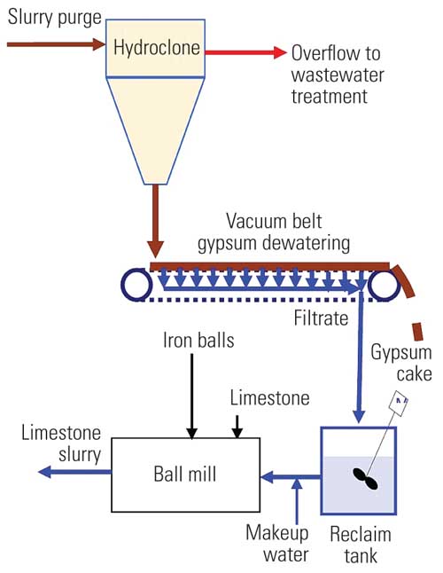
2. FGD purge gypsum dewatering system. In a typical gypsum dewatering system particles in the purge are classified, or separated, into coarse and fine fractions. Fine particles are separated in the overflow from the hydroclone to produce an underflow that consists mostly of large gypsum crystals (for potential sale) that can be dewatered to a low moisture content with a vacuum belt dewatering system. Source: CH2M HILL
Some FGD systems use gravity thickeners or settling ponds for solids classification and dewatering, and some use centrifuges or rotary vacuum drum dewatering systems, but most new systems use hydroclones and vacuum belts. Some may use two hydroclones in series to increase solids removal in the dewatering system. A portion of the hydroclone overflow may be returned to the FGD system to reduce wastewater flow.
Purging may also be initiated when there is a buildup of chlorides in the FGD slurry, necessitated by limits imposed by the corrosion resistance of the FGD system’s construction materials.
FGD Wastewater Characteristics
Many variables affect FGD wastewater composition, such as coal and limestone composition, type of scrubber, and the gypsum-dewatering system used. Coal contributes acidic gases — such as chlorides, fluorides, and sulfate — as well as volatile metals, including arsenic, mercury, selenium, boron, cadmium, and zinc. The limestone contributes iron and aluminum (from clay minerals) to the FGD wastewater. Limestone is typically pulverized in a wet ball mill, and the erosion and corrosion of the balls contribute iron to the limestone slurry. Clays tend to contribute the inert fines, which is one of the reasons that wastewater is purged from the scrubber.
The other common reason for purging wastewater is the buildup of chlorides, which are typically limited to 12,000 mg/l, based on the metallurgy used in the scrubbers. With corrosion-resistant metallurgy, chlorides up to 35,000 mg/l can be handled, thus reducing wastewater production.
There is no consistency in the definition of wastewater produced by an FGD system. Some designate hydroclone overflow as wastewater, whereas others that use a thickener or settling (gypsum stacking) pond designate effluent from these to be wastewater. Some may employ primary and secondary hydroclones to maximize the capture of solids before gypsum dewatering. Plants that produce wallboard-quality gypsum will wash the gypsum and reject more solids to wastewater. Therefore, FGD wastewater may contain as much as 7% suspended solids (if primary hydroclone overflow is used) or as little as 30 ppm of suspended solids (when using thickener or stacking pond overflow). Moreover, because it is common for a plant to change coal and limestone suppliers, the wastewater constituents will change over time during operation of the FGD system. Complicating matters further, the plant’s wastewater treatment system must be flexible enough to handle these varying inputs yet produce a treated stream that meets the plant’s wastewater discharge permit requirements.
FGD treatment systems are usually designed before any wastewater is available for testing. Therefore, much effort is expended in obtaining accurate limestone and coal analyses and estimating how much heavy metals will end up in the wastewater. From a treatment standpoint, soluble concentrations are of most interest, as particulate metals can be easily removed by simple solids removal processes.
Developing Design Guidelines
There is a growing body of data on the characteristics of FGD wastewaters taken from different points in the wet FGD system. CH2M HILL contacted the Electric Power Research Institute (EPRI), FGD wastewater treatment equipment vendors, and scrubber manufacturers for typical FGD wastewater composition for seven different FGD systems (Table 1).
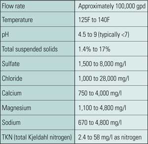
Table 1. Typical composition of FGD wastewater. The major chemical constituents found in samples taken from seven wet flue gas desulfurization (FGD) systems are summarized in this table. Suspended solids concentration varies widely, and treating for its removal dominates the treatment process selection options. Other constituents are shown as soluble, because once the solids are handled, the soluble constituents determine treatment requirements. The water is supersaturated in calcium sulfate and is hot, mildly acidic, and corrosive. Source: CH2M HILL
The wastewater data summary illustrates the variety and complexity of wastewater constituents across the industry. Four of the samples were of wastewater that had undergone settling before the collection point, so these were not analyzed for total constituents. For the other four sites, total and soluble (filtered) analyses were performed. Pond and thickener effluents were not included, as these are considered to be wastewater treatment systems in their own right, and they would have skewed the data to the low side.
In a review of metals data from these plants (Figure 3), soluble iron ranged from about 0.1 to 1 ppm, with this representing about 1% of the total iron in the sample. Boron was the metal with the highest concentration, and all of the boron was soluble. Two metals of particular interest are mercury and selenium. Mercury was mostly in the form of particulates, with soluble concentrations ranging from about 0.1 to 10 ppb. Selenium was mostly soluble and ranged from 0.1 to 1.0 ppm.
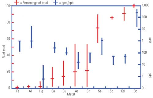
3. Typical metal concentrations in FGD wastewater. Generally, FGD treatment systems are designed before any wastewater is available for testing. From a treatment standpoint, information about soluble concentrations is what’s most needed, as particulate metals will come out in solids removal processes. Blue lines represent the range and median concentrations of soluble metals. Red lines represent the soluble fraction of the total metals in the sample (soluble plus particulate). Source: CH2M HILL
Some general conclusions can be drawn from this brief study of FGD wastewater characteristics. The most obvious conclusion is that there is no one-size-fits-all FDG wastewater treatment facility. In general, our analysis of these samples also found that:
-
There are high concentrations of total dissolved solids, principally consisting of chloride, sulfate, bicarbonate, calcium, sodium, potassium, and magnesium.
-
There is a high total suspended solids (TSS) level, due to gypsum solids, fly ash, and limestone inert material.
-
There is high buffering, due to bicarbonates and dissolved carbonic acid.
-
They are supersaturated with calcium sulfate.
-
The temperature was as high as 140F.
-
There is a potentially high organic concentration from dibasic acid addition.
-
They contain ammonia, from the ammonia slip for electrostatic precipitator conditioning and NOx control, and nitrates (as a result of incomplete selective catalytic reduction).
-
They contain miscellaneous regulated heavy metals and trace constituents (including arsenic, mercury, selenium, and boron), which vary by coal type; these metals seem to be concentrated in fine solids.
-
Hydroclones separate FGD purge water into an underflow stream that is predominately gypsum solids and an overflow stream that consists of immature gypsum crystals, inerts from limestone, and a concentration of metal solids higher than that in the underflow.
-
Metals vary: They may be present in soluble form (that is, able to pass through a 0.45-µm filter) or particulate form.
-
Selenium is present mostly in soluble form at concentrations up to several parts per million; it is being regulated to parts-per-billion levels.
-
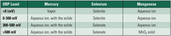
High-soluble selenium in newer forced-oxidation scrubbers appears to be due to the conversion of selenium into the oxidized selenate form, which is difficult to treat.
-
Mercury tends to be present predominately in particulate form, but its soluble fraction is in the low parts-per-billion range; it is starting to be regulated to parts-per-thousand levels.
FGD Wastewater Treatment Processes
Because of the highly complex nature of FGD wastewater, several stages of treatment are required to treat wastewater blowdown from a FGD scrubber so that it the wastewater meets regulatory requirements for surface water discharge. Typical loading rates for these processes are shown in Table 2. FGD wastewater treatment (Figure 4) typically consists of the following seven steps, which were also selected to remove heavy metals:
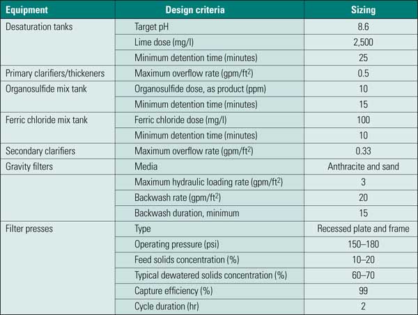
Table 2. Typical loading rates for FGD treatment. Source: CH2M HILL
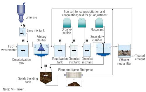
4. A typical FGD wastewater treatment plant. Source: CH2M HILL
-
Calcium sulfate (gypsum) desaturation
-
Primary clarification
-
Equalization
-
Trace metals precipitation and suspended solids removal
-
Secondary clarification
-
Filtration
-
Solids dewatering
The specifics of each treatment step are discussed in the following paragraphs.
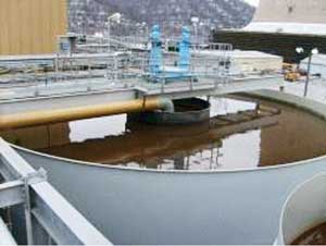
Calcium Sulfate (Gypsum) Desaturation. FGD wastewater tends to be supersaturated with gypsum, which tends to precipitate out and form scale on the surface of treatment units and inside pipes (Figure 5). To reduce the tendency of the water to scale, it is typically treated with lime (Ca(OH) 2) to reduce the concentration of sulfate by precipitation of calcium sulfate. Desaturation is performed as soon as possible to take advantage of the reduced solubility of gypsum at elevated temperatures.
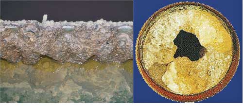
5. Mineral scale formation on clarifier overflow weir and process piping. The tendency of gypsum to continue precipitating can result in significant scale formation on surfaces of treatment units, such as the overflow weirs of clarifiers and the insides of pipes. Courtesy: CH2M HILL
The goal of desaturation is to reduce the concentration of sulfate without precipitating a significant amount of calcium carbonate. At laboratory temperature, the pH that results in the maximum desaturation without significant calcium carbonate precipitation is about 9.2. However, as the temperature rises, the solubility of calcium carbonate also decreases. The result is that the same dose of lime that would achieve a pH of 9.2 in the laboratory will raise the pH of the FGD wastewater only to around 8.2 or 8.4 at 130F. It is therefore advisable to perform jar tests of desaturation at the temperature expected in the desaturation tank, rather than relying on laboratory tests performed at lab temperature. This can be done by conducting jar testing in a water bath. If purge water tanks are outdoors, the wastewater temperature can vary considerably from winter to summer, and the dose or pH set point should be adjusted accordingly. Even though pH set point is a convenient way of controlling calcium dosing, lime dosage is the important control.
Desaturation may not be feasible if the sulfate concentration of the blowdown is high. One FGD system produced wastewater with a soluble sulfate concentration of between 20,000 and 30,000 mg/l of soluble sulfate, probably due to burning low-sulfur coal with very low chloride content. Low chloride content results in less hydrochloric acid to neutralize in the flue gas, resulting in less calcium dissolved from the limestone. With this concentration of dissolved sulfate, it may not be feasible or desirable to desaturate the water, as the resulting calcium demand will be too great to satisfy with lime, and a large quantity of gypsum and calcium carbonate sludge would be generated.
Recycling sludge from the primary clarifier has been found to be beneficial in gypsum desaturation. Recycling encourages crystallization of gypsum and growth of particles. The fine particles get a second chance to grow by fresh precipitation of calcium sulfate on their surfaces or by combining with other particles to form larger agglomerates. Moreover, in one application where we compared solids particle size distribution with and without recycling, recycling reduced the number of small particles by 75% and the weight (or volume) of small particles by 98%. This reduction in particles of the smaller size results in improved clarifier performance and sludge dewaterability.
Primary Clarification. FGD wastewater can vary widely in suspended solids, depending mainly on the methods chosen by the FGD system vendor for gypsum dewatering. Mechanical dewatering has consisted of centrifuges and rotary vacuum drums in the past, although vacuum belts are typically used today.
To attain low moisture content in a large-capacity gypsum-dewatering system, the purge water is first treated to remove fine particles of immature gypsum crystals, clays, and other inert materials using a single-stage or a dual-stage hydroclone. Where single-stage hydroclones are used and gypsum is to be sold, the hydroclones may be set to minimize fines in the underflow, resulting in TSS in the wastewater (hydroclone overflow) as high as 7%. Where gypsum solids are to be disposed of and secondary hydroclones are used, TSS can be less than 2% in the wastewater (secondary hydroclone overflow). The treatment plant designer must account for the effect of aging on hydroclone efficiency. At one plant, the overflow TSS measured in excess of 10% in overflows when the hydroclones drifted out of calibration.
Where gypsum dewatering is carried out using a stacking pond — that is, a pond where the gypsum solids are deposited and dredged into piles for gravity drainage — the ponds will remove a large portion of the wastewater TSS, and the wastewater (overflow from pond) can have much less than 2% TSS. A general rule of thumb has been to use a primary clarifier if the TSS in the wastewater is ever going to be greater than 2%. If stacking ponds are used, primary clarification may not be required. If hydroclones are used to separate fines from the purge water, then treatment should include primary clarification.
Primary clarifiers for FGD wastewater treatment are designed as sludge thickeners, with a steeply sloped floor and high-torque mechanisms (Figure 6). It is more desirable to have high-torque capability than to have a clarifier rake mechanism lifter, because one of the properties of lime gypsum sludge is to form a solid that may set before the mechanism can be lowered and restarted.
6. Primary clarifier with gravity inlet. Courtesy: CH2M HILL
The goal of primary clarification is not to remove all suspended solids but, rather, to reduce TSS to less than 1,000 mg/l so that subsequent treatment can be optimized to remove the remaining solids and other elements (metals) requiring removal.
Optimally, solids should thicken to approximately 10% to 20% solids in the underflow from the primary clarifier/thickener. Less than 10% solids can result in poor dewatering, high-moisture sludge cake, sludge sticking to filter cloths, increased operator attention, and long cycle times. If sludge is greater than 20% solids, dewatering will be hampered by poor distribution of sludge to a filter cloth and plugging of sludge distribution piping. Overthickening can be prevented by controlling the sludge recycling rate or sludge wasting.
Clarifier performance and solids density can be improved by recirculating sludge from the primary clarifier to the desaturation tank to promote the growth of particles as gypsum is precipitated when lime is added. A variable sludge recycling rate is desirable, as too much recycling can result in solids overloading of the clarifier, particularly if particles that are less than 20 µm in diameter predominate. Initial operation may be at low rates to avoid overloading the clarifier with solids, and the flow rate may be increased when a denser sludge is produced.
It is desirable to flush the sludge lines when the sludge pumps are shut down to reduce the tendency of these lines to plug. It is best if sludge recirculation and wasting is combined in a single system so that sludge pumps and lines do not need to be turned off during normal operation.
Clarifier performance can also be enhanced by adding polymers. It is therefore prudent to include a flocculation well in the primary clarifier and to provide the ability to add polymer at this point. Polymers may not be needed if sludge recycling effectively promotes a dense sludge. Care must be taken not to overfeed polymers (particularly anionic polymers), because this can cause blinding of filter press cloths. Polymer addition should be considered supplemental to achieving a dense, fast-settling particle through sludge recycling and use of low-shear sludge pumping and reactor mixing. High-speed mixing to optimize polymer addition should not be used at the expense of generating dense sludge. Polymers capture solids but tend to trap water in the resulting matrix, thereby reducing the density of the resulting sludge.
Primary clarifiers must be sized for solids-holding capacity as well as for hydraulic overflow. A peak overflow rate of 0.5 gallons per minute per square foot (gpm/ft 2) with one unit out of service (for more than one treatment train) seems to be sufficient for solids settling. But it may not provide enough sludge storage, particularly when treating high-solids wastewater with low sludge densities. Sludge wasting should be based on density of the sludge (maintaining this between 10% and 20% for optimal dewatering). Sludge level measurement seems to be of limited usefulness, as there is a broad range of densities that look the same to the eye or to an optical instrument. Measuring sludge density at a fixed depth would be more useful in controlling sludge wasting.
Mixing is critical within all mixing tanks in the process. If mixing is insufficient, larger particles settle out, adversely affecting chemical mixing and pH control. If there is too much mixing, particles shear will reduce the effectiveness of downstream removal. Higher-speed mixers can be used in traditional chemical mix tanks, where hydraulic detention times are less than one minute, but most of the reaction tanks in an FGD system have design hydraulic detention times from 20 minutes to an hour, which means much higher times at low flow rates. Radial flow impellers (Figure 7) or axial flow impellers designed specifically for low-shear flocculator applications should be used. Impeller tip speed should be limited to less than 3 feet per second.
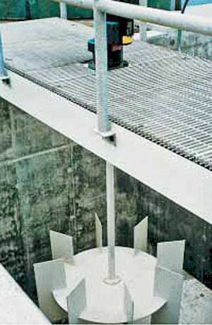
7. Axial flow flocculating mixer. Courtesy: CH2M HILL
Equalization. There are significant advantages to equalizing the waste stream before and after desaturation and primary clarification. Equalization is best designed in conjunction with the gypsum dewatering system rather than as an independent process within wastewater treatment. Equalization should be designed to provide continuous flow to the treatment plant. Internal recycle flows are better directed to an intermediate equalization tank; however, ultimately, either can be modified effectively.
Equalization serves three functions in wastewater treatment:
-
It reduces the variability of flow, which reduces the loads on treatment processes and enables the use of smaller treatment systems than would otherwise be required to handle peak loads.
-
It reduces the variability of wastewater composition, further improving the stability of treatment processes, particularly when chemical additions are needed to respond to changing requirements.
-
It allows for the storage of intermittent internal wastewater flows.
Traditionally, equalization is placed at the beginning of a treatment train, and this is the case at most FGD wastewater treatment plants. Providing equalization prior to primary clarification has some benefits, including providing a constant flow to the desaturation tank with sludge recycle. Loading the primary clarifier with solids over the short period of a day makes controlling sludge solids and dewatering difficult.
When the FGD system is located some distance from the wastewater treatment plant, it is desirable to locate any purge water storage (for equalization) at the FGD system and then pump a continuous flow to the wastewater treatment plant. If initial equalization is considered, it should be compared to the advantages of increasing volume for primary clarification, as increasing primary clarifier volume increases the volume available for sludge storage and thickening as well as hydraulic capacity.
It can be desirable to locate all or some equalization volume after primary clarification. For FGD systems where purge solids are high, the internal recycle streams (filter backwash water, filter press filtrate, filter press cloth wash water, storm water from process areas, washdown and floor drain water, sludge line purge water, and the like) can be greater than the purge flow, with much of the water returned as relatively low-solids filtrate. If returned to an initial equalization tank, this flow increases the hydraulic load on desaturation and primary clarification, eliminating the load reduction gained by putting in an equalization tank and diluting the solids that must be thickened again.
When FGD wastewater is desaturated before equalization, the water can be treated at a warmer temperature, where the solubility of gypsum is lower. After cooling, the increased solubility of gypsum reduces subsequent scaling potential. Moreover, if low-salt wastewater streams (such as storm water, filter cloth wash water, and floor drain and washdown water) are introduced after desaturation, the scaling potential is further reduced.
It is also desirable to provide for flushing of pipes containing high solids when flow is shut down in these lines. This can be automated using a flushing water system and control valves. If equalization is placed after primary clarification, then this relatively low-solids water can be used for flushing, with "dirty flush water" returned to this equalization. This practice results in the water not having a hydraulic load on the treatment units, as would be the case if final effluent (or plant water) were used for this purpose and were returned to an initial equalization tank.
Trace Metal Precipitation and Suspended Solids Removal. Metals in FGD wastewater are present in a soluble or particulate form. The soluble fraction is somewhat arbitrarily defined as whatever passes through a 0.45-µm membrane filter and consists of those species that are present as single ions or molecules that are truly dissolved, as well as (colloidal) particles smaller than 0.45 µm. The 0.45-µm filter was developed for microbial analysis, as it is a size that captures all bacteria, and the filter has been adopted for water and wastewater analysis.
Metals removal consists of taking cationic (positively charged) metal ions and combining them with anions to form solid precipitates. For most metals, the anion used is hydroxide, resulting in a mixed metal-hydroxide precipitate. The solubility of metals is dependent on the concentration of hydroxide, and metals generally are less soluble at higher pH. However, when excessive hydroxide is available, the result is formation of a negatively charged metal hydroxide molecule, and solubility increases at higher pH.
With metals being regulated to parts-per-billion or parts-per-trillion levels, it would be difficult to have a common pH for precipitation of a mixed metal waste given metals’ wide range of solubility (Figure 8). However, the low solubility of metal sulfides can be exploited. The most insoluble metal sulfide is mercury sulfide, or cinnabar. The theoretical solubility of cinnabar is so low that it would take more than 300 liters of water to dissolve one molecule.
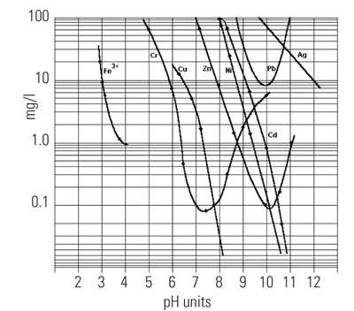
8. Solubility of cationic metal hydroxides as a function of pH. Source: CH2M HILL
Exploiting the low solubility of metal sulfides is difficult, paradoxically due to the low solubility of the metal sulfides. Because the metals’ solubility is so low, metal sulfides rapidly precipitate, forming particles that are so small that they are essentially soluble. As a result, there have been various attempts to develop larger organic molecules with sulfide-like functional groups. These include solids (ion exchange media) as well as chemicals that can be added to a wastewater to precipitate cationic metals.
One of the earlier forms of organosulfides for metals precipitation in wastewater was dithiocarbamate (DTC). DTC is a relatively small molecule, and metal precipitates tend to be relatively fine. DTC was therefore limited to use in combination with microfiltration. Control of dosing relied on oxidation-reduction potential measurement. Because some DTC usually ended up in the effluent, problems were encountered with effluent toxicity.
One organosulfide that was promoted by Degussa Chemical for treatment of mercury in FGD wastewater is TMT-15. This compound is reported to be less toxic than DTC and is effective at treating mercury to parts-per-billion levels with conventional suspended solids removal processes (flocculation, clarification, and media filtration).
Both TMT-15 and DTC are monomers, and their size may explain why they do not remove mercury down to the theoretical solubility of mercury sulfide. Some of the precipitated mercury organosulfide is likely to be present in particles smaller than those that can be removed by conventional solids removal methods. Analysis of mercury in various treatment systems has shown that there is a considerable amount of mercury present as particles smaller than 0.45 µm.
Nalco developed a polymeric organosulfide with a molecular weight of between 2,000 and 5,000 that is marketed under the NALMET trademark. Nalco reports that NALMET reduces soluble mercury concentrations to the tens of parts per trillion, reportedly because it acts as a coagulant as well as a precipitating agent. Plans are under way to test this agent on an FGD wastewater to determine if NALMET can be optimized further.
Metals removal can also be enhanced over that achieved by metal hydroxide precipitation through iron coprecipitation. In this process, iron is added in concentrations much higher than the trace metals targeted for removal. Iron coprecipitation removes anionic metals as well as cationic metals, with cationic metals favored at high pH and anionic metals favored at lower pH. As the ratio of iron to trace metal increases, so does removal efficiency. With FGD wastewater, primary treatment acts as a pretreatment step, employing metal hydroxide precipitation to lower metal concentrations. Secondary treatment is then needed to polish or achieve lower concentrations of metals.
After metals precipitation, the resulting suspended solids (along with residual suspended solids in the primary effluent) are coagulated to produce larger particles for removal by settling and filtration. Ferric chloride is typically used as a coagulant for this purpose, along with cationic and anionic polymers. Ferric iron has the advantage of also providing iron coprecipitation to enhance trace metals removal. Ferric chloride acts as an acid, lowering the pH from the level used in desaturation. Additional acid may be added to optimize coagulation and metals removal. Selenite removal with iron is favored at pH below 6.5.
Metal precipitation and coagulation reactors should be designed with flocculating mixers, to minimize shear, which produces fine solids that are then difficult to remove. This may not be a factor if only solids are to be removed to 30 mg/l, but now that metals are regulated to parts-per-billion or parts-per-trillion levels, even a small loss of metal precipitates can be significant.
Secondary Clarification. Secondary clarifiers should be limited to an overflow rate of approximately 0.33 gpm/ft2. If the clarifier is to be located in a building, consider lamella clarifiers, as they have a smaller footprint. However, lamella clarifiers have limitations that need to be overcome or accepted if they are used.
The effective overflow rate (compared to conventional clarifier) should be reduced to less than 0.2 gpm/ft2 due to higher velocity between the plates. Lamella clarifiers tend to be tall, and so all mix tanks need to be elevated, with gravity flow in straight pipes between mix tanks to reduce shear.
Sludge volume is limited in a sludge hopper, so a larger thickener bottom is recommended to provide sludge volume adequate to have effective sludge recirculation to the iron mix tank. Sludge recirculation must be optimized and polymer addition minimized to produce a solid that will slide easily down the lamella plates. Otherwise, the sludge may tend to stick to the plates, causing sudden breakthrough of solids and a frequent maintenance job of draining the water level below the plates and cleaning them.
Several Filtration Options. Filtration is a necessity if metals removal is required. Sand filters can reduce TSS to 1 ppm and generally remove solids that are 5-µm and larger. Filters, however, are prone to scaling. Scaling can be reduced, but not eliminated, if hydrochloric acid is used for pH control instead of sulfuric acid. Filters add to the complexity of the process and increase all of the treatment unit sizes because of backwashing. If TSS is greater 100 mg/l, then backwashing becomes so frequent that the plant can become overloaded.
Membrane filtration is being used more frequently for metals removal. However, membranes are more prone to scaling and are also sensitive to polymer use in the plant. As the pore size decreases, the head loss increases and flux decreases, adding to the size and cost of the technology. Membranes are therefore showing great promise when ultralow metals concentrations are required.
In addition to organosulfide treatment, some non-FGD wastewaters have been successfully treated with ion exchange resins with sulfide functional groups. Due to the high affinity of mercury for sulfides, these expensive resins (up to $2,000/ft 3) are not regenerable and therefore are best used for applications with low-flow wastewaters, such as discharge from dental sinks.
Selenium removal is broken into selenite and selenate treatment. Selenite treatment is difficult but has been shown to work using iron hydroxide sorption. This process is effective over the narrow pH range of 6 to 6.5. Selenate removal for FGD wastewater is more problematic, as selenate is not removable by iron precipitation at any pH.
Of the developing selenium removal processes, the most advanced is the ABMet Process (Figure 9) owned by GE Water, which was pilot tested with FGD system wastewater over five months. A few full-scale systems have been installed and are in early stages of operation. The ABMet process uses two-stage anoxic reactors. The first reactor was used to denitrify nitrates in the wastewater as well as reduce some of the selenium to elemental selenium. In the second stage, the remaining selenium was reduced. Results of pilot testing were very positive (Figure 10).
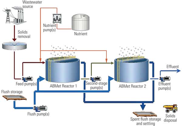
9. The GE Water ABMet process flow diagram. Source: GE Water
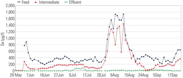
10. Pilot plant selenium removal data for ABMet treatment of FGD wastewater. Source: CH2M HILL
Solids Dewatering. Sludge is produced in primary and secondary clarification. There are three main technologies for sludge dewatering: centrifuge, belt press, and plate-and-frame press (Table 3). Although there are three possible technologies, the choice is typically between a belt press and plate-and-frame press, as centrifuges tend to experience excessive wear when treating typically abrasive power plant solids. Also, centrifuges tend to segregate solids by size, with the centrate returning the fines to the process. This results in building fines in the treatment process, which has adverse results on performance.
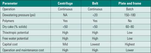
Table 3. Comparison of sludge dewatering equipment. Source: CH2M HILL
Gypsum solids tend to be thixotropic in the 50% solids range, which means the solids tend to take the shape of and stick to the container in transit, thereby making them difficult to remove. Transit by truck also tends to release water from belt press – dried sludge, which may create a disposal problem. This problem can be solved by mixing fly ash or gypsum with the dewatered cake to soak up free liquids.
The initial cost of belt presses is lower than that of plate-and-frame filter presses, but the former require more operator attention and polymers, and they produce larger volumes of dry cake, which means plate-and-frame presses have lower lifecycle costs.
Different positive displacement pumps have been used to achieve the high pressure needed for sludge dewatering. Typically, a centrifugal sludge pump is used for rapidly filling the largest presses. Progressive cavity pumps have been successfully used for other sludges, but the abrasive character of power plant sludges results in excessive wear. Air-operated diaphragm pumps cannot achieve the required pressure for dewatering and are short-lived.
Hydraulic membrane pumps have been effective, if preventive maintenance is scrupulously performed. At one plant, a hydraulic membrane pump failed rapidly due to check valve chatter when it was installed with a sludge tank high level that was higher than the filter press. The failed pump was replaced with two centrifugal pumps in series. When these pumps are operated with variable-frequency drive controls, the pumps combine the ability to provide rapid filling at low pressure and can ramp up pressure as the sludge cake forms. Final pressure is achieved by turning on the second pump. One caution is to control speed to achieve the required pressure rather than having pressure used to then adjust speed. The latter approach can result in rapid oscillations in both pressure and speed.
When sludge is maintained at a good density range (10% to 20% solids) through adequate lime dosing and sludge recirculation, and care is taken not to use excessive anionic polymer, then cake will dewater quickly to 60% to 80% solids and will drop off the cloth with little, if any, prodding (Figure 11).
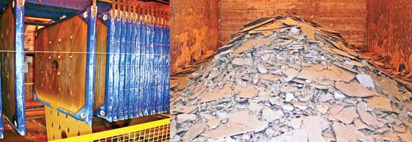
11. Squeeze play. Plate-and-frame filter press (left) and resulting dewatered cake (right). Courtesy: CH2M HILL
–Thomas E. Higgins, PhD, PE (thiggins@ch2m.com) is vice president and technology fellow; A. Thomas Sandy, PE (tsandy@ch2m.com) is technology director of the Industrial Systems Business Group; and Silas W. Givens, PE (sgivens@ch2m.com) is vice president and director of Industrial Water and Wastewater for CH2M HILL.