After building three 1,000-MW dual-fuel simple cycle plants, each with eight combustion turbines, Mass Global Holding Ltd. recently repowered the Erbil Gas Power Station, located in Iraqi Kurdistan, using vertical heat recovery steam generators, adding 500 MW of capacity to the local grid.
Iraqi Kurdistan, located in the northeast corner of Iraq, is nation building. The country has an independent government, maintains its own army, flies its own flag, speaks it own language, and recently began directly selling its oil on the global market, to the dismay of the Iraqi government. Kurdistan may not be a free state, but it operates as a free market.
The Kurdistan Regional Government’s (KRG) heavy investment in infrastructure over the past decade is another important sign of its autonomy. Prime Minister Nechirvan Barzani affirmed the KRG’s commitment to long-term electrification projects because they “will fuel further development in other sectors [of its economy] as well.”
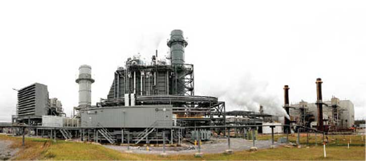
Independent power producer Mass Global Holding Ltd. (MGH), headquartered in Amman, Jordan, is a company that has heavily invested in the future of Kurdistan. MGH has built, owns, and operates about 3,000 MW of combustion turbine (CT) power generation in Kurdistan, the largest of which is the Erbil Gas Power Station (EGPS), located about 22 kilometers south of the capital city of Erbil (Figure 1). In August, U.S. airstrikes prevented the group calling itself the Islamic State of Iraq and Syria (ISIS) from entering Erbil, and Kurdish Peshmerga forces have pushed the militants away from the city, although at the time of this writing, ISIS remains in control of the northern city of Mosul.
 |
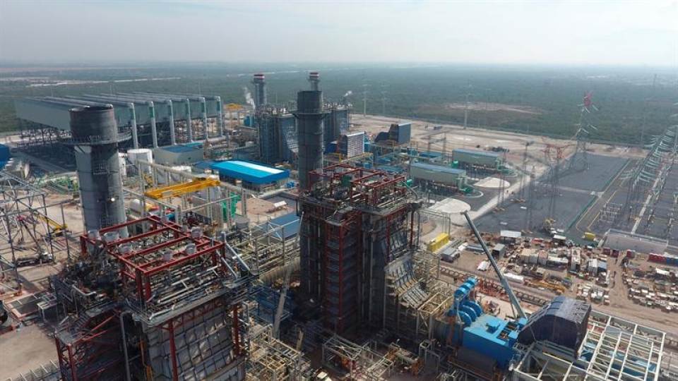
| 1. Phased construction. The Erbil Gas Power Station was constructed in three phases. The first and second phases each consisted of four GE Frame 9E combustion turbines (CTs). Phase 3 added eight CMI Energy heat-recovery steam generators (HRSGs) and two GE steam turbines, forming two 4 x 1 power blocks. The plant, rated at approximately 1,500 MW in combined cycle mode, is the largest power plant in Iraqi Kurdistan. Courtesy: CMI Energy |
Development of EGPS Phase 1 began in January 2007 with the installation of four GE Frame 9E multi-shaft CTs with a total capacity of 500 MW. Phase 1 was completed in May 2008. In 2011, the completion of Phase 2 added another four CTs and increased the plant’s capacity to 1,000 MW, making it the largest power plant in Kurdistan and its first combined cycle plant. The dual-fuel simple cycle CTs can operate on natural gas or diesel. Gas reaches the station from the Khormor gas fields, while trucks deliver the oil to five 4,000-m3 fuel tanks.
EGPS Phase 3, now in the final stages of commissioning, converted the simple cycle CTs into two 4 x 1 combined cycle power blocks, raising the station capacity to 1,500 MW. The majority of the electricity is consumed in Erbil, although earlier this year KRG had begun exporting electricity north to Mosul and south to Kirkuk, helping to alleviate power shortages in those regions while increasing revenues for Kurdistan. However, a mid-September news story reported that the Iraqi Kurdistan government had cut off electricity to Mosul and the surrounding areas, which were controlled by ISIS militants.
Phase 3 added eight CMI Energy dual-pressure heat-recovery steam generators (HRSGs), two nominal 250-MW GE C-7 steam turbines (STs), and two GEA Energietechnik 40-cell air-cooled condensers (ACCs) that operate at 0.0666 bara (1.97 in Hga) at 15C ambient. ABB Sweden provided and built a new 400-kV substation to interconnect the STs with the Kurdistan national grid. The completion of Phase 3 improved the thermal efficiency of the plant to about 55% to 56%, thus making EGPS one of the most efficient power plants in Iraq. The 500 MW added by Phase 3 provides approximately 15% of the power demand of the Kurdistan region. Turkish constructor ENKA Construction & Industry Co. (ENKA) was selected by MGH to build Phase 3 on an engineering-procurement-construction (EPC) basis.
One of the key design requirements for the project is that the plant may be dispatched in any combination of baseload operation throughout its service life. That means that each power block may be dispatched independently, but in addition, each CT within a power block may be started or restarted depending upon the grid requirements at the time, with a minimum of two CTs operating in a power block. This mode of operation places significant demands upon the HRSG.
HRSG Design Features
There are two principal HRSG configuration options used today. Horizontal arrangements have been traditionally favored in the U.S., while vertical arrangements are commonly found in Europe and Asia. Both arrangements are found behind “E” and “F” class CTs and are comparable in performance. However, the horizontal version is generally considered to have a slight advantage when using duct firing and in catalyst arrangement. The vertical version has improved accessibility, greater flexibility in internal arrangement of heat transfer surfaces, greater resilience when used in cycling or load-following service, and eliminates the need for a crane to lift modules into place. In addition, the vertical HRSG is favored for plants burning heavy fuel oil, as it is more easily cleaned with sootblowers.
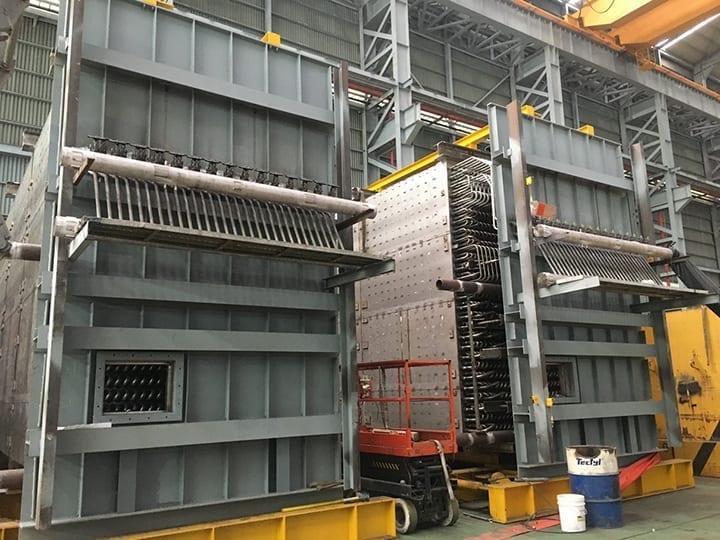
The most striking difference between the two HRSG arrangement options is in the constructability of the unit. Instead of lifting individual modules into place using a heavy crane, the vertical HRSG modules are lifted into place using a trailer and temporary hydraulic jacks, starting with the economizer, and suspended by a series of top support hangers (Figure 2).
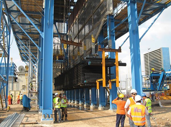 |
| 2. Modular lifts. Converting existing simple cycle CTs to combined cycle usually means working within a very congested project site. The prefabrication tube modules for a vertical HRSG can be maneuvered around site obstacles and put into place using a self-propelled hydraulic trailer, thus eliminating the need for a crane. At Erbil, each HRSG module was lifted into place using hydraulic jacks located on the top of the HRSG support structure. Each vertical HRSG used on this project has eight prefabricated modules that were jacked into place in less than one week. Courtesy: CMI Energy |
The typical horizontal HRSG is designed with numerous headers on opposite ends of each vertical tube module or platen. Venting occurs at the top header, and the bottom headers are drainage points. The top and bottom headers require jumper piping.
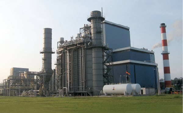
Conversely, a vertical arrangement consists of individual modules with a single inlet and outlet header, with the “jumper pipes” replaced by shop-welded elbows. The entire module is then hydro tested between a single inlet and outlet header before shipment. Boiler drums sit independently on the steel superstructure, and field welding consists only of the inter-module piping connections and connections to the boiler drums, significantly simplifying the erection process. The high level of shop fabrication of tubes, components, and other sub-assemblies for EGPS reduced the time and construction labor required to erect each HRSG (Figure 3). Prefabrication also reduces the logistical challenge of moving large quantities of raw materials long distances over difficult terrain.
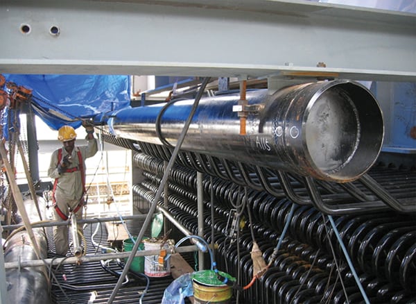 |
| 3. Minimize field welds. Once a module is lifted into place and secured, the single inlet and outlet headers are welded together. Note the absence of “jumper pipes” and headers common on horizontal HRSGs. The elbows were shop welded and the complete module hydro tested before leaving the factory. Courtesy: CMI Energy |
Accessibility is greatly improved in a vertical HRSG arrangement. There are access doors strategically located on its casing so that an inspector can easily reach any location on a module without scaffolding by standing on the module’s horizontal tubes. Headers are also accessible from inside the HRSG casing.
The vertical arrangement is also more forgiving when there is a failure in a specific tube in a module. Because the drums are located away from the tube bundles and return bends are without intermediate headers, specific tubes can be extracted from a module and replaced in the field. The serpentine configuration of the vertical HRSG has a good track record on cycling operation because the tube modules have flexible return bends instead of fixed headers, allowing free expansion of the tubes, much like a feedwater heater.
The vertical HRSG is designed for thermal cycling. A HRSG must be purged of any lingering explosive gases prior to restart. This means the CT supplies the purge air by blowing relatively cold air through the hot HRSG for several minutes prior to a CT restart. Inside the HRSG, the cold air quenches the superheater, forming condensate inside the tubes that drains and thermally shocks the bottom headers on a horizontal HRSG. Any accumulated water within the bottom header must be drained to prevent any condensate carryover into the superheat piping that can thermally shock and deform downstream tubes. In the vertical HRSG, the superheater outlet header is the single low point in the system that collects any condensate formed, preventing condensate carryover by design. Horizontal HRSGs are configured with many large drains beneath the superheater and reheater bottom headers to prevent condensate carryover.
Phased Conversion
Phase 3 included erecting the HRSG, STs, and ACCs in the midst of an operating plant, connecting the HRSGs through a diverter damper during a short outage, followed by startup of each power block in combined cycle mode.
One challenging problem was making the physical connection of the CT to the HRSG connection flange prior to HRSG erection on a very tight schedule. The existing CT stack structures were reconfigured by replacing the casing elbow with a new CMI-provided shop-prefabricated “T” box with integral diverter damper on each of the eight CTs during sequential CT outages to minimize downtime (Figure 4). The first CT was completed in three days; subsequent units were completed in only two days each. Each CT was restarted when its diverter damper was completed, and the CTs continued to operate in simple cycle mode during the subsequent erection of the HRSG (Figure 5). The conversion process went smoothly because provisions for the diverter damper conversion were included in the original stack structural design, minimizing impact on the existing stack.
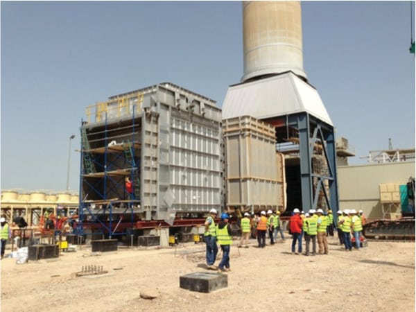 |
| 4. Damper remodel. The existing 9E CTs exhaust through a stack in simple cycle mode. Converting the units to combined cycle required removal of the casing elbow and installation of a new “T” box with a diverter damper. The first conversion was completed in only three days. In this photo, the old “T” section has been pulled from beneath the stack and will soon be removed from the rails. The diverter damper section in the foreground is sitting on the rails, ready to be slid into place. Courtesy: CMI Energy |
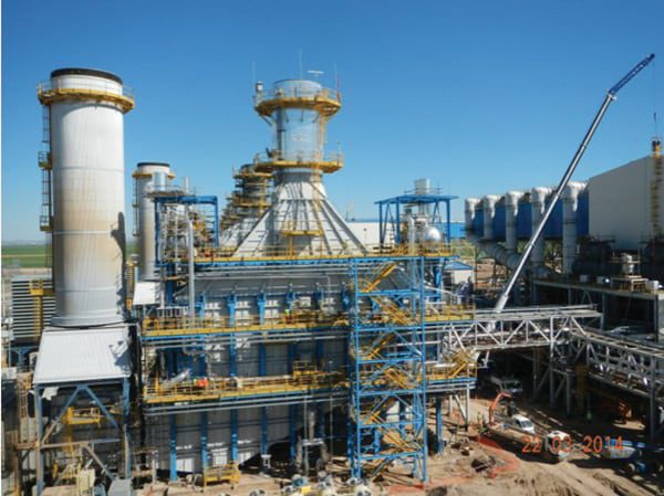 |
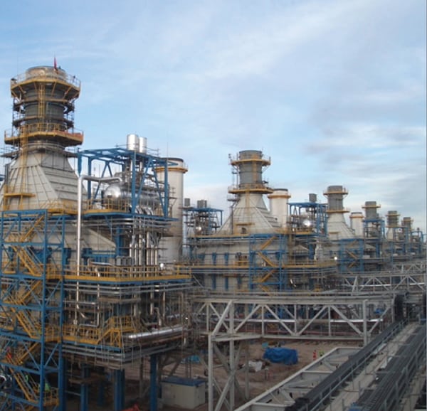
| 5. Flexible operations. One of the eight HRSGs is shown with the CT on the far left, with the diverter damper and bypass stack shown between the CT and the HRSG. The diverter damper allows operation of the CTs in simple cycle mode by bypassing the CT’s exhaust gases before entering the HRSG. Courtesy: CMI Energy |
The HRSGs installed during Phase 3 are dual-pressure (high-pressure [HP] and low-pressure [LP] superheat sections) without reheat, a common arrangement with the 9E configured in a 4 x 1 power block. The main steam conditions are 77 bara at 520C at 50.93 kg/s for the HP and 8.2 bara and 219.9C at 10.96 kg/s for the LP superheat. The main steam produced by each HRSG in a power block is fed to a common header that goes to the ST. A minimum of two CTs must be in operation to produce sufficient steam for the ST and for the power block to remain in service.
Training of the plant staff was also a priority for the project team. CMI Energy developed a training program tailored for the operation and maintenance of the plant’s HRSG system. Two courses were presented, each five days long.
The KRG’s critical need for additional power accelerated the project schedule after work on the contract commenced in April 2012. Working closely with ENKA and other supplier subcontractors, CMI was able to fast-track its engineering, raw material procurement, and shop fabrication work, thus accelerating onsite erection by two months. Steel erection began in April 2013, the first hydro test was completed in December 2013, and first firing took place in January 2014.
MGH has signed contracts with Enka and CMI to similarly repower its Sulaymaniyah and Duhouk plants, also located in the Kurdistan region of Northern Iraq. Each of the two plants is now in the process of being repowered from simple cycle (eight Frame 9E CTs producing 1,000 MW) to combined cycle (1,500 MW) operation. The Sulaymaniyah project began construction in July 2013 and is expected to be complete in early 2016. The Duhouk project began in October 2013.
Even after completing these three projects, the potential for repowering simple cycle CTs in Iraq is enormous—provided security of the facilities can be ensured. The latest information indicates there is another 4,000 MW to be captured simply by repowering existing simple cycle CTs. We will surely see many new repowering projects on the scale of EPGS in the coming years. ■
—Dr. Robert Peltier, PE is POWER’s consulting editor.