How to Prevent Circulating Water Flow Reversal
Flow reversal in piping systems can degrade equipment performance and cause significant water hammer, potentially resulting in catastrophic failure. Power plant condenser cooling water systems—or circulating water systems—are especially prone to reverse flow. The advantages and disadvantages of various valves used to prevent reverse flow are presented in this article to help readers select appropriate solutions to avoid trouble.
Flow reversal is a serious problem that can occur in piping systems with parallel pumps or in systems that pump uphill. When one or more pumps trip out of service, the loss in pressure can cause reverse flow to form based on the piping’s elevation, slope, flow resistance, and pressure differential.
Circulating water (CW) pumps used for condenser cooling are normally the largest pumps at a power station, commonly delivering flows of 150,000 gallons per minute or higher. If a CW pump trips, reverse flow, water hammer, backwards pump rotation, pump over speed, pipe over pressure, pipe vacuum pressure, cavitation, or a forced steam turbine shutdown can occur.
Reverse flow protection requires more thought than simply installing a conventional check valve. This article will describe the problems that reverse flow can cause and show examples of various effective solutions.
Understanding Circulating Water Systems
Power station CW pumps deliver cooling water to steam turbine condensers. The CW pumps are commonly high-specific-speed, low-head, high-flow designs. Systems come primarily in two basic configurations (Figure 1).
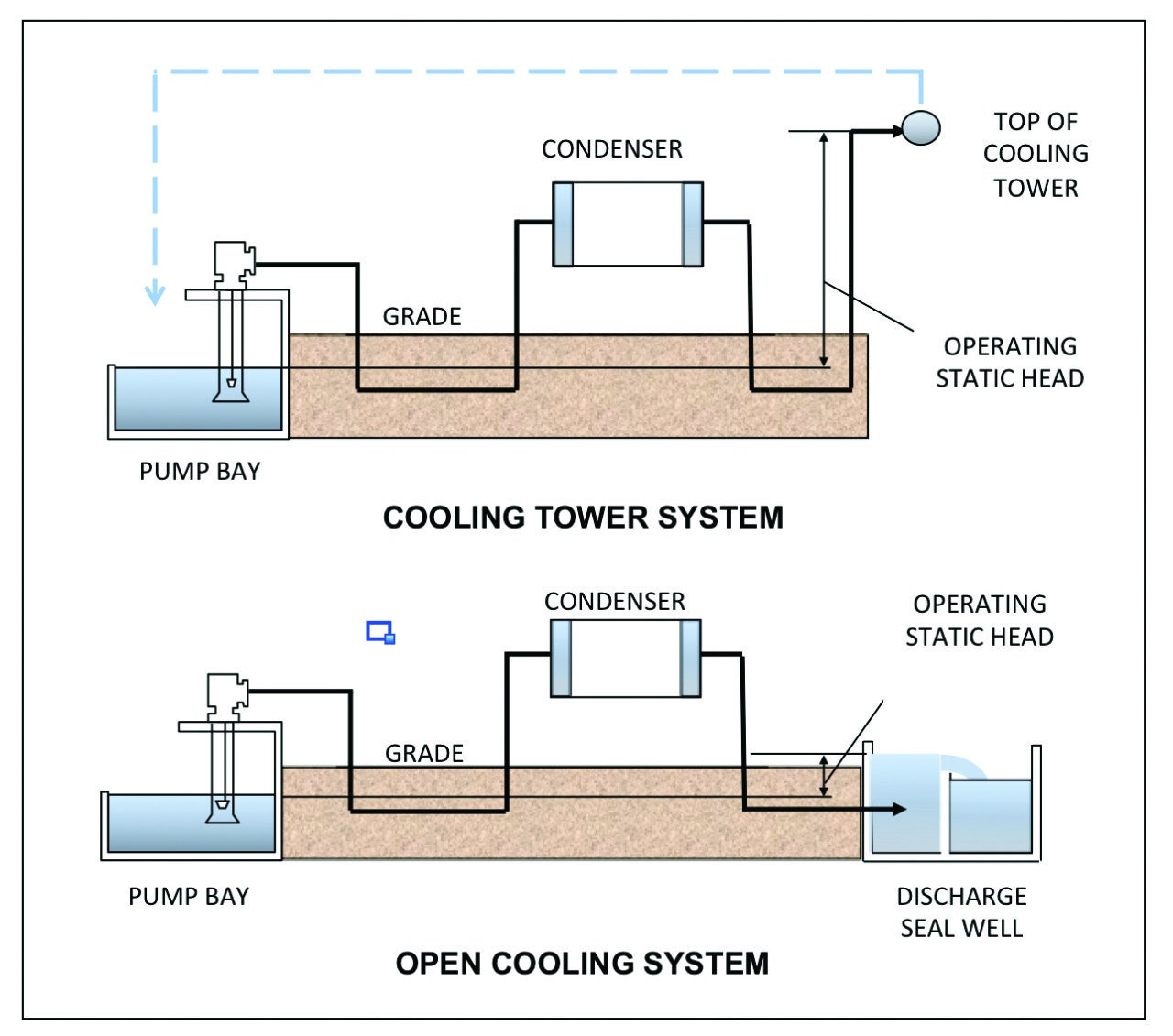 |
| 1. Two standard configurations. Most power plants use either the cooling tower design or the open cooling design for steam turbine condenser circulating water systems. Source: Michael F. Czyszczewski |
If the heated water exiting the condenser is discharged, the design is known as an open cooling system. Alternatively, a cooling tower system reuses the heated water. Both configurations pump uphill. The most important difference, related to reverse flow, is that an open cooling design operates with a lower operating static head and, therefore, has a lower potential for reverse flow and water hammer.
Most CW systems have two or more operating pumps. The worst-case scenario is when all of the operating pumps simultaneously trip, such as following a complete power failure. The sudden loss of CW pump pressure combined with a low static head pressure, uphill pumping, and a routing that has intermediate high points creates a high potential for water hammer.
A sudden loss in pump pressure generates a large down-surge (negative pressure wave), which travels downstream at the acoustic (sonic) velocity of the water. This wave will reflect, reverse, and split into more waves at branches and pipe diameter changes. Soon, positive and negative pressure waves will be traveling throughout the system, crashing into pipe bends and fittings. Pipe overpressure and unrestrained movement can damage the piping, hangers, and attached equipment.
If the down-surge drops the pressure to the water vapor pressure (full vacuum), the water will start to vaporize. When an up-surge occurs, the pressure increase will cause the vapor bubbles to implode. That is known as cavitation, and it can erode internal piping and component surfaces.
Stopping Reverse Flow
The most common device used to prevent reverse pipeline flow is a check valve (also known as a nonreturn valve or zero-velocity valve). Most check valves begin to close when the forward flow velocity is approaching zero and the downstream pressure exceeds the upstream pressure. The valve disk opens when these conditions reverse.
A power-assisted valve (PAV) can also be used to prevent reverse flow. Unlike a check valve, a PAV does not start closing at the time of flow reversal, but rather, is programmed to start closing when the pump trips. Once closed, it does not begin to reopen until the pump starts.
PAVs and some check valves can be specified to close at two speeds. For example, the operator can be programmed to close quickly to about the 20% open position and then close much slower through the remaining distance. The initial fast speed helps to minimize backflow through the valve, while the following slow speed minimizes the water hammer potential.
If the valve is opened or closed by a motor operator, a power source is needed. High-torque applications may require a hydraulic operator. In case of a power failure, a battery power source, a design that fails closed, or a pneumatically powered system could be used.
Due to the large diameter of CW piping, a butterfly valve is typically the lightest-weight, lowest-cost PAV option.
Equipment Concerns
If an event occurs that trips one or more pumps, but not all of the pumps, the amount of reverse flow that occurs while the valve is closing may be large enough to cause equipment performance problems. Before selecting a valve, the following issues should be considered.
Condenser Vacuum Loss.CW systems are designed so that sufficient flow to the condenser is possible with one or more pumps out of service. However, backflow through a slow closing valve after a pump trip will cause additional loss of condenser cooling water flow. Although temporary, this loss may be enough to cause the steam turbine to trip on high backpressure.
The minimum acceptable flow rate to the condenser along with the backpressure alarm and trip settings (generally 5–11 inches of mercury absolute (in-HgA) to alarm and 8–12 in-HgA to trip at full load) should be obtained from the steam turbine manufacturer. If the allowable flow rate and backpressure are not available, an estimate of condenser performance can be calculated by using guidelines from the Heat Exchange Institute “Standards for Steam Surface Condensers” or another heat exchanger design guide. It is not uncommon for the alarm pressure to be exceeded, but backflow should not reduce CW flow enough to trip the turbine.
Pump Runout.CW pumps are designed to remain operating if one or more pumps are taken out of service. However, backflow from the operating pumps through a tripped pump will temporarily further reduce system resistance, causing the performance of the operating pumps to runout on their curves to higher flow rates. Higher flows may result in operation out of their operating range and off the pump curve, which can lead to cavitation, vibration, and possibly overloading of the motor.
If pump runout conditions are possible, valve closing time should be decreased to minimize backflow through a tripped pump, or the pump manufacturer should be consulted concerning the runout condition.
Backwards Pump Rotation. Reverse flow will make an unpowered centrifugal pump spin backwards. These pumps are not designed to rotate in reverse, and can be damaged if they reach a backward speed much greater than their forward design speed. High-vibration, undesirable stresses, and detrimental loads on the motor, bearings, and other components could result.
The Hydraulic Institute, a North American association of pump industry manufacturers, publishes allowable back-speed limits that could be used, if the original pump manufacturer does not provide limits. Higher specific speed pumps are more tolerant of high back-speed. If the allowable back-speed is exceeded, a shorter valve closing time should be specified, or the pump should be supplied with a reverse speed prevention (ratchet) device.
Pump Restart. If tripped pumps are reenergized before the flow has been given time to stabilize, the up-surge in pressure can trigger water hammer. Any trapped vapor cavities that collected at system high points will violently collapse due to the pressure increase. The pressure waves generated may shake and overstress the piping and damage it, as well as restraints and connected equipment.
Computer Modeling. Reverse flow is best studied with the help of a commercial transient (water hammer) software program. Applied Flow Technology’s (AFT’s) Impulse software was used to create the figures for this article, but many other software packages are available. Most programs use the “method of characteristics.” Incidentally, the models for open cooling and cooling tower configurations were constructed for illustration purposes only.
Choosing the Right Check Valve
An ideal check valve would close instantly at the time of flow reversal. Real check valves, however, take a finite time to close. During this time, some backflow will occur through the valve and a pressure wave will be produced upon valve closure (Figure 2).
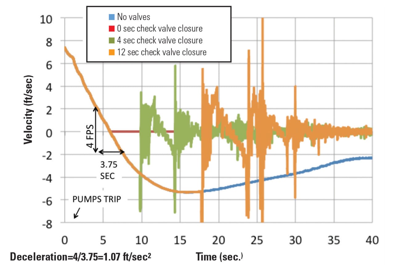 |
| 2. Effects of check valve closing time differences. This chart shows the effects that different check valve closing times have on the pressure wave created in circulating water systems. In this example, flow reaches zero about six seconds after the pump trips. With no valve installed, reverse flow peaks in 16 seconds and then slowly stabilizes. When the valve closes instantly, no reverse flow occurs. However, in the 4- and 12-second valve closure scenarios, potentially damaging pressure waves are created in the system. The best real-world design would minimize the pressure wave while preventing reverse flow. Source: Michael F. Czyszczewski |
No Flow Restriction. This is a baseline case illustrating unrestricted flow without a check valve. The velocity steadily drops after the pump trip and reverses direction after 6 seconds. At the time of reversal, the flow is decelerating at 1.07 ft/sec2. The reverse velocity reaches a maximum value in approximately 16 seconds and afterwards begins to slow and stabilize.
Valve Closes Instantly. A check valve will begin to close when the flow velocity is zero. An “ideal” check valve would close instantly at that time. As shown in Figure 2, no pressure wave occurs under this scenario.
Valve Closes After Flow Reversal. Real check valves experience a lag time before they begin to close, since a minimum pressure differential must first be overcome. To illustrate more realistic valve behavior, an example is shown in which closure begins when the flow velocity drops to zero, but it takes four seconds for the valve to close completely. Backflow will occur through the valve during this time, a pressure wave occurs at the moment of complete valve closure. The magnitude of the pressure wave is a function of the reverse velocity that would have occurred without the valve closing. A 12-second closing scenario is also shown in Figure 2.
Manufacturers have devised various designs in an attempt to achieve ideal check valve performance. Valves can be purchased with disks that have low inertia, are axially mounted, or travel only a short distance.
Some valve types can be immediately excluded from consideration for practical reasons. A 72-inch swing check valve may be impossible to find, and if one is located, it may be too large, slow, and heavy to be practical.
The moving disk in valves with a long lag time, or which move slowly, will be subjected to higher reverse flow velocities. A high flow velocity will accelerate the disk and slam the valve shut. This phenomenon is known as check valve “slam” and is a common cause of water hammer.
If there is a possibility of severe check valve slam, specify a design using a damper or spring to cushion the disk travel just before complete closure. These valves are known as “silent” or “quiet” check valves.
In order to help with selecting an appropriate valve type, many manufacturers and water hammer reference books publish versions of reverse velocity versus deceleration curves based on work by A.R.D. Thorley, whose “Check Valve Behavior Under Transient Flow Conditions: A State-of-the-Art Review” was published in the Journal of Fluids Engineering in 1989. In general, the curves indicate that check valve slam potential is not a concern if the valve closes before the reverse velocity reaches 0.5 ft/sec and will have only a mild slam potential up to velocities of 1.0 ft/sec (Figure 3).
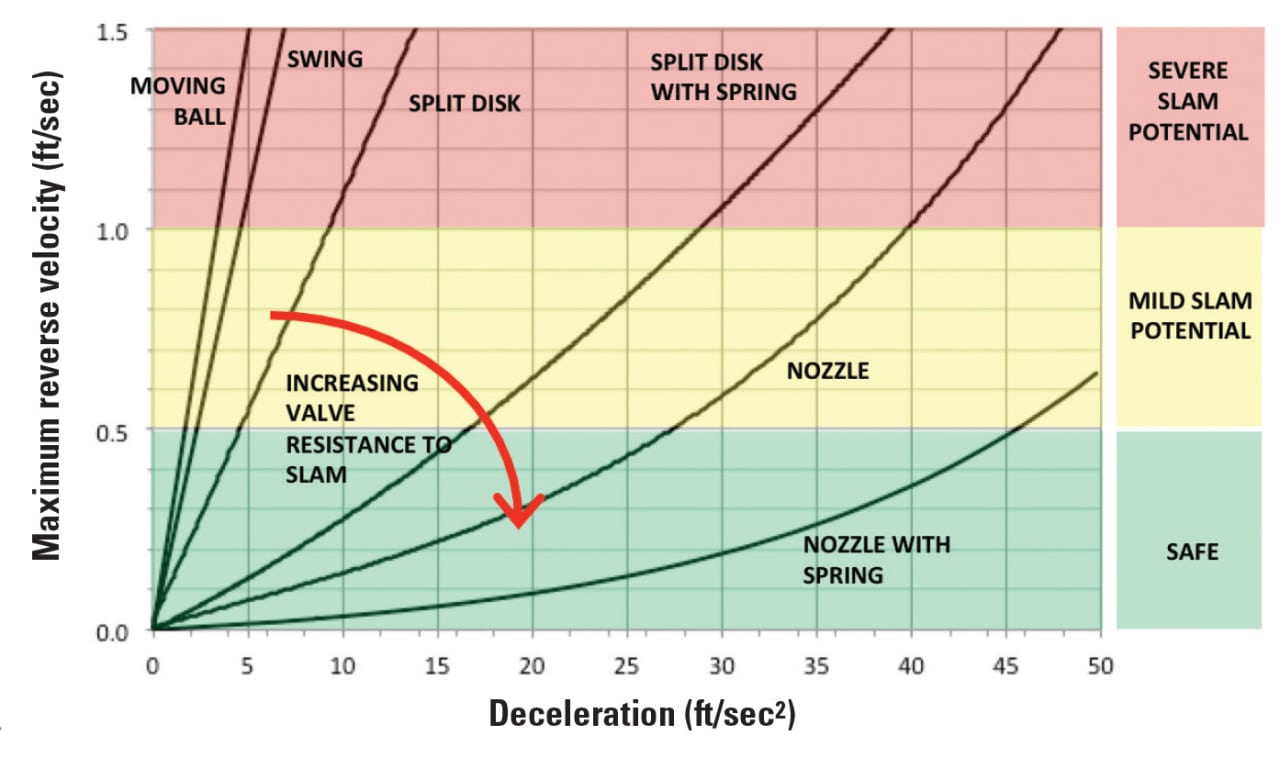 |
| 3. Reverse velocity versus deceleration curves. In general, check valve slam is not a great concern as long as reverse velocity remains less than 0.5 ft/sec. Source: Michael F. Czyszczewski |
For example, if a computer model of a system without check valves indicates flow deceleration is 20 ft/sec2 at the time of flow reversal, using the Thorley curves you find that a split-disk check will allow a velocity of up to 0.6 ft/sec before closing. That is only slightly in the zone that indicates a mild slam potential and could be considered acceptable. However, if there was a concern, a more slam tolerant valve type such as a nozzle check could be selected to drop the potential for slam into the safe zone. The maximum valve closing time to use in the computer model would be the time that it takes to go from zero velocity to the velocity obtained using the Thorley curve.
Check valves do not provide positive shutoff. A check valve will reopen whenever the inlet pressure exceeds the outlet pressure enough to overcome the disk’s lifting velocity. Therefore, isolation valves must be provided downstream of the check valves.
The PAV Alternative
The maximum and minimum acceptable PAV closing times can be found by making a series of test runs using a computer model (Figure 4).
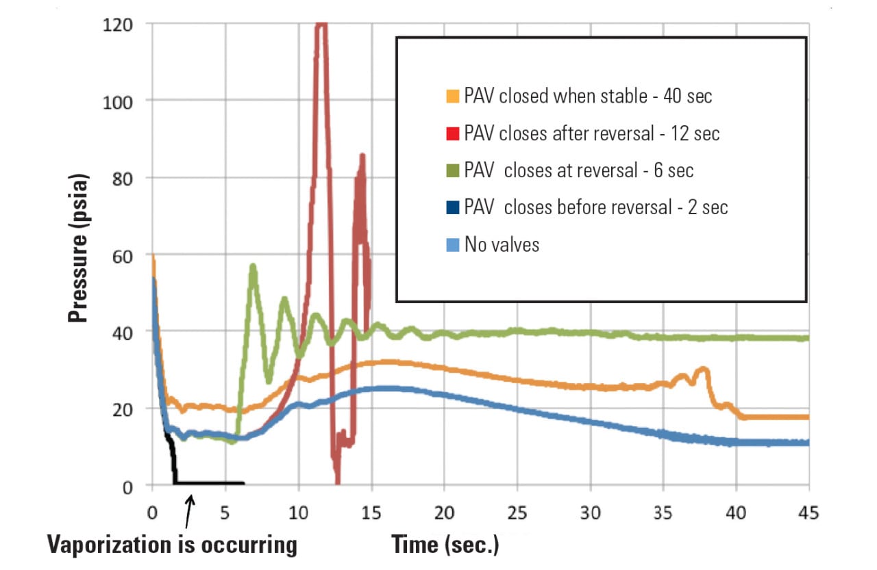 |
| 4. Pressure versus time. The chart shown here compares the pressure-time history near the pump discharge for different pressure-assisted valve (PAV) closing times when all pumps trip in an open cooling system model. Source: Michael F. Czyszczewski |
No Flow Restriction. This is the baseline case illustrating unrestricted flow without a PAV. The pump pressure rapidly drops in about one second. Although the drop is steep, the pressure always remains above atmospheric.
PAV Closes Before Flow Reversal.Closing the valve before the flow reverses, such as two seconds after the pump trip, will create a low-pressure zone on the downstream side of the valve and a high-pressure zone on the upstream side. It is very common for pressure to drop to near full vacuum on the downstream side as shown in Figure 4 by the flat line near 0 psia. Full vacuum pressure will cause the water to vaporize and cavitate. If significant vaporization occurs and forms into a vapor cavity, water hammer can occur when the flow reverses and collapses the vapor space.
PAV Closes at Flow Reversal.Having the valve close at the predicted time of flow reversal (six seconds in the Figure 4 example) shows only a small pressure spike. This case is similar to that of the ideal check valve, except that the earlier start of valve closing causes a slight shift in the time of flow reversal.
PAV Closes After Flow Reversal.The pressure spike generated at valve closure increases in magnitude as the lag time increases. In this example, a 6-second lag between flow reversal and valve closure, creates a spike of about twice the normal operating pressure.
PAV Closes When Flow Is Stable.Predictably, extending the valve closing time into the period when the flow has become stable does not produce a pressure spike.
Based on these observations, the minimum PAV closing duration should be the approximate time of flow reversal determined by the analysis. The maximum time should be based on consideration of the equipment performance issues described earlier. Longer times are preferable to shorter times, so pick a time at the long end of the range.
Restarting one or more pumps too quickly could result in a pressure surge. In general, a pump should not be restarted until after it has stopped spinning and its discharge valve has finished closing. Pump restart computer simulations should be used to determine the minimum permissible pump restart time. In parallel pumping systems, the restart times should be staggered to avoid surges. The PAV opening speed is typically specified to be the same as the closing speed.
Combining Options
Some CW installations have both a check valve and PAV installed downstream of each pump. This arrangement performs primarily like a check valve installation. The check valve is the first line of defense against reverse flow, and it will passively react and close based on the fluid velocity and differential pressure. The PAV provides backup protection against reverse flow in the event that the check valve sticks open. Some other benefits of this design include:
■ Starting a medium-specific-speed pump against a closed valve will reduce the power required to start and will also prevent pump runout. If there is a concern that the motor could be overloaded by running the pump “dead headed” against a closed valve, the pump start can be momentarily delayed until the valve is about 10% open.
■ The PAV also provides positive flow isolation required for pump maintenance. No manual isolation valves are required.
The PAV closure time is not critical unless there is a possibility that a pump trip could develop an oscillating wave in the sump that will cause the check valve to repeatedly cycle between open and closed. If the computer model shows that type of behavior, the PAV should be specified to close shortly after the check valve closes.
Clearly, both check valves and PAVs alone are capable of preventing reverse flow. Installing both is somewhat redundant. The redundancy may be justified in situations where the benefit of having high reliability is important (Table 1). However, this benefit comes with greater complexity and component cost.
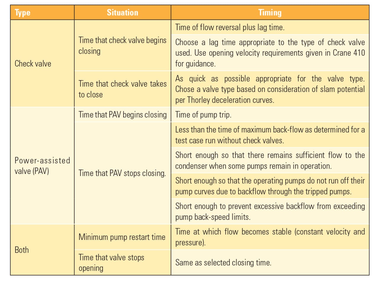 |
| Table 1. The skinny. This table summarizes valve-timing recommendations when using check valves, power-assisted valves, or both to prevent reverse flow in circulating water systems. Source: Michael F. Czyszczewski |
Other Considerations
When the CW pumps trip, the pressure may drop to near full vacuum at the pump discharge. Adjustments to the check valve or PAV closing time are not always sufficient to raise the pressure above full vacuum and prevent cavitation from occurring. In those cases, a vacuum breaker (air-inlet) valve is needed to raise pressure by automatically admitting air when a vacuum is detected.
The pump discharge and condenser outlet are areas prone to full vacuum pressure due to their high elevation. A computer model is an ideal tool for determining if vacuum breakers are needed and how to size them. However, a discussion of vacuum breakers and air valves is beyond the scope of this article. If these valves are needed, readers should discuss sizing options with a reputable equipment manufacturer.
There are additional methods for mitigating pump trip and reverse flow transients that are not presented here. They include the use of surge tanks, changes to the pump motor inertia, adding pump bypass lines, using pressure relief valves, or installing surge anticipation valves.
Most options offer some cost and performance advantages and disadvantages. Some installations have unique configurations or operating conditions that may require investigation of these other alternatives. However, it has been the author’s experience that installing a single-speed, butterfly-type PAV at each CW pump discharge is the simplest and most cost-effective solution for the majority of cases, which might be encountered. Computer modeling of complex hydraulic transients is the best way to evaluate the options and ensure a problem free design. ■
—Michael F. Czyszczewski ([email protected]) is a senior-level mechanical engineer with 40 years of experience working at Sargent & Lundy on the design and specification of power plant components.