Much like the crime scene investigators on the CSI TV shows, power plant investigation teams are increasingly employing forensic engineering methods to gather evidence and determine the causes of malfunctions of equipment, materials, or products that result in personal injuries or property damage. Case studies show how different investigation teams used their forensic engineering expertise to examine a dust collector explosion, a coal terminal fire, and the failure of a forced draft fan.
It’s common for a power plant that has experienced a serious fire, explosion, or equipment failure to assign a cross-functional team to conduct an investigation. A recent development, however, is investigation teams’ increasing use of sophisticated forensic engineering techniques when they conduct inquiries into serious incidents at power plants that involve personal injuries or damage to property.
Forensic engineering is the investigation of products, materials, structures, or components that fail or do not function properly and, as a result of such malfunctions, cause personal injuries, property damage, or monetary losses to a business. This discipline involves retracing processes and procedures related to accidents in the operation of machinery, products, structures, or components.
Many universities and training facilities now offer courses on incident investigations, which usually incorporate forensic engineering methods. Such training typically covers the principles of incident investigation, the responsibilities in the investigation process, investigation planning and preparation, the tools and techniques used in investigations, the collection and examination of information, root cause analysis, preparation of the incident investigation report, and effective real-world corrective actions (see "Lessons Learned from a Hydrogen Explosion," POWER, May 2009).
The forensic engineering process can be applied in civil law cases, although it also may be used in criminal lawsuits. In particular, the law of products liability deals with the consequences of failure of equipment and machinery in the civil law arena.
The application of forensic engineering ranges from investigations in industrial settings such as electric power plants to inquiries into incidents involving individuals in automobile accidents that are suspected to have been caused by malfunctioning vehicles. Typically, the individuals or teams who conduct such forensic engineering inquiries seek to find the cause or causes of failure in order to improve the performance or extend the life of a machine or piece of equipment, or to help a court of law in determining the facts related to an accident.
In the context of power plants incidents, such inquiries usually involve either a knowledgeable team of plant personnel who use forensic engineering methods while conducting their incident investigation or the facility hiring a consulting engineer who has been trained and certified as a forensic engineer to lead the investigation efforts (see sidebar).
Following are case studies of actual incidents that occurred at three different U.S. power plants. The investigation teams looking into these three events used forensic engineering methods to uncover the underlying causes of each incident and provide formulated recommended corrective actions to prevent similar incidents from happening again at these facilities.
Miller Electric Generating Plant Dust Collector Explosion
Marley Perkins, the fire protection team leader at Georgia Power Co.’s Plant Scherer, presented an overview of the Miller Electric Generating Plant dust collector explosion at the 2009 ELECTRIC POWER Conference. The following profile of the incident is based upon his presentation.
James H. Miller, Jr. Electric Generating Plant is located along the Black Warrior River near West Jefferson in Alabama (Figure 1). Owned by Alabama Power Co., the coal-fired plant first went into service in 1978 with the completion of the first of four 705.5-MW generating units. Additional units were brought online in 1985, 1989, and 1991. The plant’s total nameplate capacity is 2,640 MW.
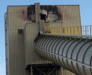
1. Explosive situation. On Feb. 27, 2006, Plant Miller, a coal-fired power plant in Alabama, had an explosion in its No. 10 dust collector on top of the yard silos. Courtesy: Southern Co.
Plant Miller has four silos located outside the plant in the fuels yard. No. 10 dust collector is located 220 feet up atop the fuels yard silos. This dust collector is used during the filling of the four yard silos. It also receives dust from three other collectors. The four yard silos are filled by a radial conveyor on top of the silos.
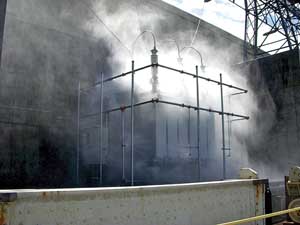
Overview of the Explosion. On February 27, 2006, at 3:24 p.m., plant employees heard a "loud boom." The fuels personnel looked up to see black smoke coming from the No. 10 dust collector on top of the yard silos (Figures 2 and 3). At the same time a high carbon monoxide (CO) alarm was received for the No. 10 dust collector. Fortunately, the CO detectors had recently been calibrated.
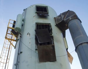
2. Dangerous discharge. The dust collector is shown after the dust explosion. The explosion relief panels are shown hanging from the openings. Courtesy: Southern Co.
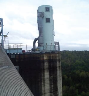
3. Back in business. The same dust collector is shown after explosion venting panels were replaced. It is located on the top of four 220-foot-tall coal silos. Courtesy: Southern Co.
The fire alarm system also indicated that the automatic sprinkler system for No. 10 dust collector had activated. This sprinkler system is designed with automatic injection of a wetting agent into the water. Coal was not being run at the time. The last train had finished dumping coal at 11:20 a.m. The No. 10 dust collector was running.
The structural fire brigade responded and, after assessing the information available, sent firefighters up to the dust collector for a closer inspection. Upon reaching the top of the silos they used a thermal imaging camera to determine there were no hot spots on the dust collector. Before proceeding further, they used a fire hose to wet down the coal dust around the dust collector. The fire brigade had the automatic suppression shut down for a moment and determined that the CO level was low and not rising.
The fire brigade then advanced a hose line up to the top of the dust collector entrance door (Figure 4). They made entry and looked for hot spots and wet the area with the fire hose and wetting agent as a precaution. They also had the hopper access panel open for inspection.
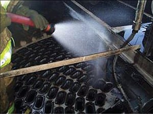
4. Taking precautions. A fire brigade member sprays water inside the top of the dust collector bags after the explosion and after the fixed sprinkler system was isolated. This was a precaution to ensure that no embers remained. Courtesy: Southern Co.
Investigation of the Incident. The plant had an employee on-site who was the root cause analysis coordinator trained to be in charge of investigations of any facility incidents. He quickly set up an investigation team to probe the causes and impacts of the explosion. After he set up the investigation team using plant personnel, the team began inspecting the dust collector at approximately 7:00 p.m. As part of this investigation they also looked at the dust collector ducts leading to this collector.
Using a thermal imaging camera and laser thermometer, they found a hot spot outside the dust collector at the backdraft damper where the 34-inch-diameter duct meets the collector (Figure 5). Further inspection of the ducts identified two bends in the duct that also had hot spots:
-
One was a 22-inch-diameter duct coming from silo #2. External temperature was recorded at 110F.
-
The other was a 22-inch-duct coming from silo #4. External temperature was recorded at 140F.
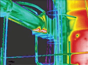
5. Highlighting hot spots. This infrared image shows the duct, backdraft damper connecting into the dust collector. This shot was taken several hours after the explosion. Note the two white spots at the backdraft damper, which show that hot spots are still smoldering. Courtesy: Southern Co.
The team gently removed both elbows and kept a fire hose standing by. The internal temperature of the smoldering coal was recorded at 500F. These hot spots were extinguished using water and a wetting agent. The backdraft damper access panel was opened, and water and the wetting agent were applied to extinguish the smoldering coal dust. The backdraft damper appeared to be operating properly.
The investigation team also requested that the manufacturer provide support regarding the incident and inspect the system. The manufacturer later sent a team of engineers to inspect the system.
Proposed Corrective Actions. The investigation team determined that airflow was out of balance, which caused some coal dust, over time, to drop out of the airflow in the two elbows. Most likely, sparks from the smoldering coal dust in the elbows were drawn into the operating dust collector. Some modifications were required to ensure that differential pressure across the dust collector bags was maintained at the proper level.
The following corrective actions were suggested by the investigation team in order to prevent similar incidents from happening in the future:
-
Allowing more time for the air purge cycle.
-
Changing one stationary hood duct from 23 inches to 12 inches.
-
Installing clean-out ports or removing certain elbows periodically for inspection of dust buildup as part of a predictive maintenance (PM) program.
-
Replacing some butterfly valves in ducts because one was missing and others did not operate properly.
-
Using a thermal imaging camera as part of normal inspection of this area, especially the ducts.
Cook Coal Terminal’s Fire
Bob Taylor, with American Electric Power’s (AEP) environmental, safety, and health organization, and Dennis Kovach, an engineer with AEP’s fire protection engineering group, presented an overview of the Cook Coal Terminal fire at the 2008 ELECTRIC POWER Conference. The following profile of the incident is based upon their presentation.
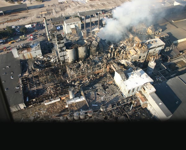
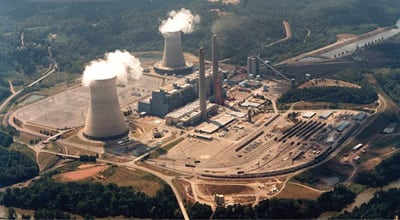
AEP’s Cook Coal Terminal is located along the Ohio River near Metropolis, Ill. It was the first utility-owned rail-to-river coal transfer terminal. It began operations in 1976 and transloads approximately 15 million tons of coal annually (Figure 6). The investigation of this incident focused on two stations: Station 1, which houses dual rotary car dumpers and conveyor 12 (455 ft long, 72 ft wide); and Station 2, which was originally designed as a crusher house (43 ft by 34 ft by 74 ft).
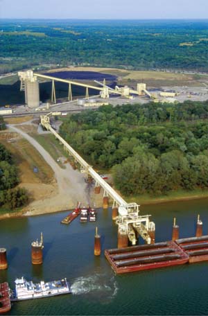
6. Cooked Cook. AEP’s Cook Coal Terminal, located along the Ohio River near Metropolis, Ill., was the first utility-owned rail-to-river coal transfer terminal when constructed in 1976. In 2007, the terminal experienced a rail car fire. Courtesy: American Electric Power
Overview of the Fire. Early in the morning on Feb. 4, 2007, facility personnel discovered a fire at the rail dumper and noticed a plastic pipe was burning. Unloading was stopped, the fire was extinguished, and unloading was restarted after about 1 hour. The south dumper was not seating properly, so unloading was moved to the north dumper at the facility.
Then personnel heard "a large boom." Fire was visible coming from the 1-1 dust collector. Workers also observed a fire located at Station 2. The fire department was called at 5:22 a.m. and the firefighters remained on scene until almost 9:00 a.m. Then, around 11:30 a.m., plant personnel observed smoke coming from the 3-1 dust collector.
Facility employees had previously retrofitted the vent doors with a cable that allows the dust collectors to be opened from a safe distance in the event of a fire. In response to the fire, personnel used this cable to open the dust collector and then used a ground-mounted monitor nozzle on the bag house to extinguish the fire. No employees were injured during this incident.
All the affected conveyors are protected with an automatic deluge system. The facility’s transfer stations have closed head sprinklers fed from the deluge system, but none of these systems activated automatically during the incident.
Investigation of the Incident. AEP quickly formed an investigation team to determine what caused the fires. The investigation team had many questions: How did the fire get to so many different places? What happened in Station 2? Why didn’t the fire system activate? How can this be prevented from happening again?
The team had the following game plan:
-
Interview key personnel who were on site the night of the fire.
-
Review each area where the fire damage occurred.
-
Review design drawings for the dust collection system.
-
Produce a written report with findings and recommendations.
The initial fire at the rail dumper started at the "bear cage" area, which is an intake to the rail dumper dust collector. This dust collector never caught fire. Several days after the fire, personnel discovered damage on a feeder belt below this area. It was unclear whether it was caused by hot coal or burning plastic.
Feeders below the rail dumper as well as Conveyor 12 are covered by the 1-1 dust collector. The team concluded that burning material was pulled into the collector where ample fuel was available. When the second fire was discovered, the vent doors on the 1-1 dust collector were already open. The team determined that most likely this was the "boom" that the personnel at the scene heard.
One of the witnesses the team interviewed commented that "Fire was dropping out of the dust chute" from the 1-1 dust collector onto Conveyor 12, which travels into Station 2. Personnel later found remnants of dust collector bags on this conveyor and also remnants on Conveyor 23. This helps to explain why the 3-1 dust collector, which pulls from this conveyor, also caught fire.
The team focused in depth upon Station 2 as part of their investigation:
-
Damaged siding at Station 2. Witnesses reported to the investigation team that the fire immediately darkened when the deluge system was manually tripped. Every upright sprinkler head on the top floor of the station was opened. The investigation team learned, however, that the fusible links from these heads had previously been removed to facilitate washdown. The investigation team found damaged siding along the south, west, and north walls of Station 2 (Figures 7 and 8). Gaps were visible in the siding along all four walls and large pieces of siding from the north and west walls were observed on the ground (Figure 9). Witnesses reported these may have been blown off by the fire department’s hose streams. Witnesses believed the fire department did not use tools such as pike poles to pull siding off. Heat damage was observed on some of these pieces.
7. The scorched south wall. The exterior south wall of Station 2 at the Cook Coal Terminal showed damage from the fire. Courtesy: American Electric Power
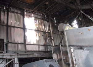
8. The fire’s aftermath. This photo shows the head chute and south wall inside Station 2, where the fire occurred. Courtesy: American Electric Power
9. A room with a new view. This photo was shot through the hole in the south wall of Station 2 that was created by the fire. Note the unburned conveyor belt in the foreground and the open equipment removal door in the background. Courtesy: American Electric Power -
Coal buildup. Ledges under the south wall of Station 2 provided minimal areas for coal buildup. The investigation team reviewed other transfer stations to confirm float dust buildup was not a problem. The team ruled out the possibility of a fire burning inside the ductwork for the 2-1 dust collector located under the south wall. Through a chute inspection door, a hang-up point with significant accumulation was found about 10 feet below the magnet at the head pulley for conveyor 12.
-
Inoperable fire detection system. The existing detection system was determined to be 31 years old. Despite the plant employees’ diligent efforts to perform PM and repairs, parts of this system were inoperable. The site was in the midst of a multi-year effort to replace its existing systems with Protectowire. Conveyor 12 had not yet been converted. Even if the system had been operable, the fire was probably would not have been large enough to activate the system until Station 2 became involved.
Tracking Down the Fire’s Origin. The investigation team determined the fire at Station 2 might have originated in the head chute. When the 1-1 dust collector explosion occurred, a large amount of burning material may have been discharged onto conveyor 12. This might explain the fire growth around the same time as the explosion, according to the team’s research.
Conveyor 12 continued to run, which should have created negative pressure pulling air into the chute. Updraft from burning material could overcome this negative pressure, but a substantial fuel load would be needed. Some observers initially believed the open equipment hatch may have contributed to the fire growth. Meteorological records, however, leave that theory in doubt.
Contradictory Theories about a Possible Dust Explosion. The investigation team tried to determine if a dust explosion had occurred at Station 2. The observed hang-up inside the head chute consisted mainly of fines (fine coal particles). A slug of burning material could have raised this dust into suspension and provided an ignition source. The investigation team found there were many observations supporting this theory. For example, they found torn siding and gaps in the siding. They also observed burn patterns on the ceiling and north wall.
On the flip side, the investigation team discovered much evidence that contradicts this theory. Melted siding shows that fire burned up against the south wall for a period of time. Siding on the south wall was not blown away from the building. Only one explosion was heard.
No security cameras were positioned to view these areas. Additionally, no witnesses could detail the beginning of events at Station 2. The investigation team concluded that without an eyewitness account, it is impossible to say exactly what the sequence of events was at Station 2. Fortunately, in spite of recent cold weather, Station 2 was still being washed down on a regular basis. Those good housekeeping practices limited damage and potentially prevented a secondary explosion.
Proposed Corrective Actions. The investigation team came up with the following recommendation to prevent future fires from happening at the Cook Coal Terminal and to more safely handle a fire should one occur:
-
Continue to fund replacement of the fire detection systems.
-
Install Class A foam proportioning capability if the existing baghouses remain in service.
-
Install CO monitors.
-
Develop a fire emergency handling procedure.
-
Evaluate the hydraulic design of the existing deluge systems due to concern about all sprinklers in the transfer houses being left open.
-
Investigate/remedy the cause of coal hang-ups in the Station 2 chutework.
-
Limit the use of combustible construction in coal-handling areas. If using noncombustible materials is not an option, provide extra attention to these areas during washdown.
-
Keep the maintenance doors closed and secured when not in use
The Failure of a Forced Draft Fan
John Amoo-Otoo, PE, senior electrical engineer at Exelon Nuclear, presented an overview of the failure of the Unit 2 forced draft (FD) fan at an undisclosed U.S. coal-fired power plant at the 2009 ELECTRIC POWER Conference. The following profile of the incident is based upon his presentation.
The coal-fired power plant where the draft fan’s motor failed consists of three steam turbines with a net generating rating of 750 MW. The units began commercial operation in 1960, 1965, and 1970. Coal is received by rail and limestone by rail or truck. Plant personnel unload the rail cars into a rotary car dumper at a rate of 20 to 25 cars per hour. A 30-day supply of coal is maintained in the on-site storage area.
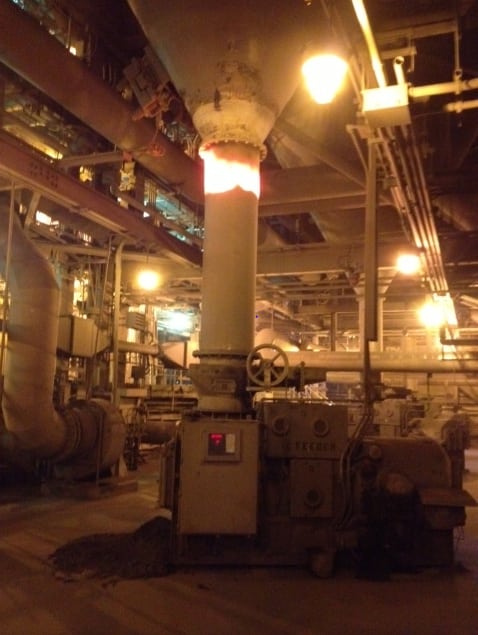
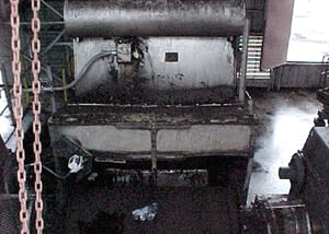
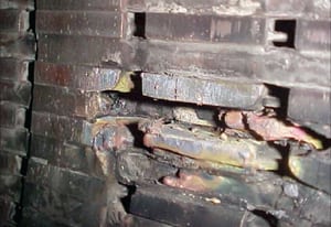
Overview of the Equipment Failure. On June 6, 2004, at 10.30 a.m., the Unit 2 FD fan motor at the facility tripped. There was a double phase to ground fault indication of the electromechanical relay. The fan motor is protected by an electromechanical relay, which has a disadvantage in respect to its capability of being used for temperature monitoring. It cannot monitor the temperature of the windings compared to multifunction relays. When the Unit 2 FD fan inadvertently failed, the fan’s motor erupted into flames. The fire caused damage to the insulation, ground wall, and the coil of the FD fan motor (Figures 10 and 11)
10. Gone up in smoke. When the forced draft fan inadvertently failed, the fan’s motor erupted into flames. The fire caused damage to the insulation, the ground wall, and the coil of the fan’s motor. Courtesy: John Amoo-Otoo
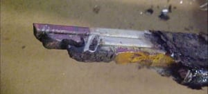
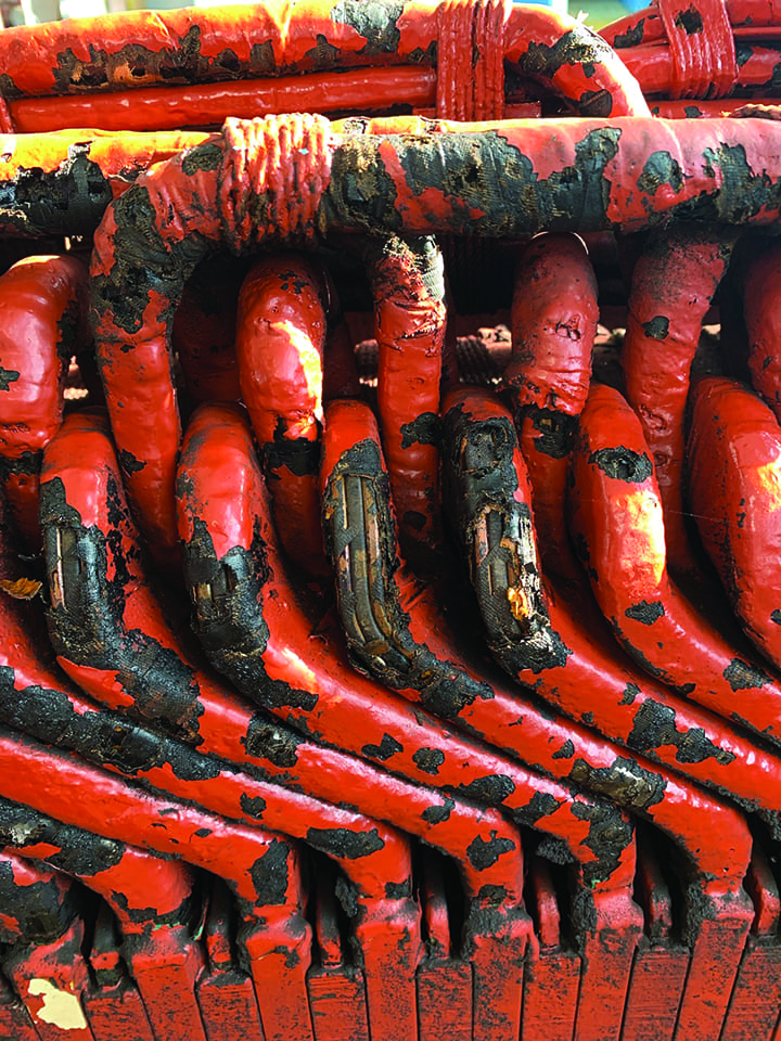
11. Cooked coil. This photo shows the damaged coil of the forced draft fan motor after it caught on fire. Courtesy: John Amoo-Otoo
Investigation of the Incident. Plant personnel formed an investigation team to determine the cause of the malfunction of the Unit 2 FD fan and to implement correction actions to prevent similar incidents from occurring in the future. The team decided to use a "root cause investigation" approach. This investigation method is highlighted in the book TapRoot: Root Cause Analysis, Problem Investigation, Proactive Improvement by Mark Paradies and Linda Unger.
Early in their investigation, the team concluded that the FD fan 2B inadvertently failed due to the destruction of a section of both the winding and the ground wall insulation of the motor, which set the motor on fire. Thermal aging of the winding insulation of high-voltage motors has prompted the team to consider ways to monitor the condition of the insulation of the winding of its 4,160-V critical motors.
The electrical insulation used in stator windings as well as the stator core laminations has a major impact on the reliability of large motors. Failure of the insulation directly or indirectly will result in the failure of the machine, which in turn will cause a forced outage or derating of a unit. Many insulation failures originate with aging that occurs over many years. To operate cost effectively, means to periodically assess the condition of insulation of the winding are needed.
The investigation team decided to take the following actions:
-
Conduct a root cause analysis of the inadvertent failure of Unit 2B FD fan.
-
Determine the steps that needed to be taken to correct the failure.
-
Implement the corrective actions.
Six main areas were determined to be the root cause of the Unit 2 FD fan’s failure: excessive heat that can lead to thermal aging and deterioration, inadequate impregnation of the ground wall, voltage surges, contamination, abrasive particles, and inadequate end winding spacing. The investigation team’s analysis showed that out of the six potential causes, three of them were the most likely causes: thermal aging, operator’s failure to follow the manufacturer’s hot start and cold start timing sequence, and excessive heat due to poor maintenance work on cleaning and changing the filters.
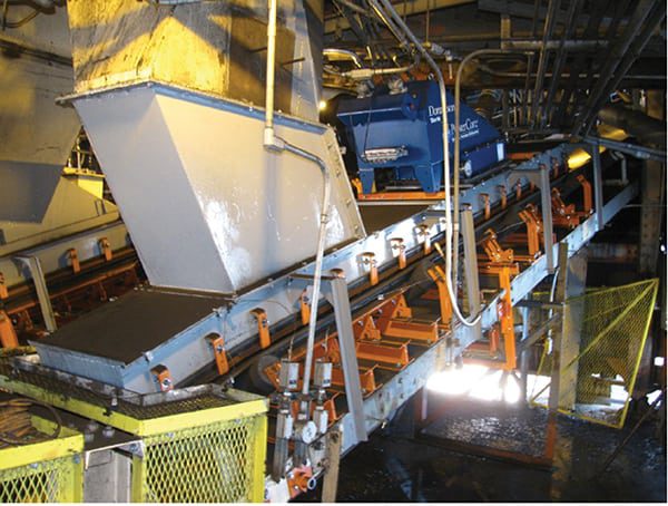
Implementation of Corrective Actions. After the incident, plant personnel immediately repaired the badly damaged insulation and winding of the motor. They later sent the damaged motor to Joliet Motors to be rewound (Figure 12).
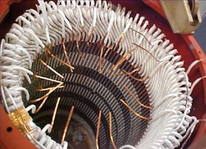
12. Good as new. After the fire, the fan’s motor was repaired with new winding and insulation. Courtesy: John Amoo-Otoo
Based upon the findings they obtained from their forensic engineering analysis, the investigation team came up with a number of corrective actions that they recommended the plant personnel implement in order to prevent future failures associated with Unit 1, 2, and 3 large motors. They suggested that these proposed corrective actions be coordinated with pre-outage and outage work. They also recommended that online testing be performed during pre-outage periods and that off-line testing be conducted during outage periods.
Plant personnel carried out the following corrective actions that were recommended by the investigation team:
-
Plant personnel awarded Illinois Electric Works the contract to conduct all the predictive maintenance testing, which provides detailed analysis of motor and circuit conditions, on all the high-voltage motors at the plant. This included off-line and online testing.
-
Resistance temperature detectors or thermocouples were installed by being embedded in the stator slots between the top and bottom bars or the coils and windings of most motor windings at the facility.
-
Approximately ten 469 relay units were installed on switchgear to protect motors from temperature excursions and to isolate the circuit. The plant also agreed to hire General Electric to train all in-house relay technicians how to set and troubleshoot the 469 relay.
-
A yearly PM program was created so that in-house personnel can periodically clean the winding, change the filters to incoming air, clean the environment, and clean the oil out of the stator winding and the ventilation.
-
Two craft personnel and an engineer from each plant were approved to go to Joliet Motors every time a motor is sent to the shop to inspect the winding during the rewound, impregnation process, and inspection of the ventilation ducts.
-
A power quality tester was installed on the motor feeder circuit to continuously measure the quality of the power and alarm an operator in the control room of any abnormality with power quality.
-
Plant personnel implemented PM for the ventilation system of the motor to ensure that it is checked, cleaned, and the filter replaced when needed.
-
PM steps were taken to check the wedges, the condition of all end-winding blocking and ties, and the tightness of supports for end turns.
-
An in-house training program was created to train the electricians how to interpret the results of the traditional Megger test and also to consult an engineer if they are in doubt.
The Growing Role of Forensic Engineering at Power Plants
In the current competitive U.S. generation market, worker safety and operational reliability are paramount concerns at power plants. Equipment malfunctions can not only cause injuries to personnel, damage valuable equipment, and interfere with plant productivity, they also can lead to costly litigation. Therefore, post-incident investigations should be thorough and timely in order to ascertain the causes of the incidents as swiftly as possible. Just as power plant personnel typically have emergency response plans in place to deal with fires or explosions, they also should be prepared to implement investigations using forensic engineering methods quickly in the event that incidents occur at their facilities.
—Angela Neville, JD, is senior editor of POWER.