The need to integrate renewable energy resources, and prepare for increased demand for power as electrification takes hold in transportation and other sectors, creates challenges for an aging grid. Some problems are being solved with the introduction of innovative equipment to upgrade the distribution network.
The U.S. power transmission grid will need to solve a multitude of challenges over the next few decades. It’s a period that will experience the integration of large-scale renewable generation to the grid, while operators are dealing with year-over-year load growth projections, a boom in electric vehicle charging stations, and commonly occurring environmental disturbances that threaten reliability and resilience.
The U.S. and other countries have accelerated the installation of new renewable energy resources, in large part due to the global concern with climate change. The power transmission grid is facing a major challenge as power producers work to reduce emissions of carbon dioxide while also meeting the demand for interconnecting these new sources of generation.
There are many roadblocks. Grid operators face the challenge of upgrading the capacity of current transmission lines, and gaining regional regulatory approval for any grid projects. There’s resistance from landowners with rights-of-way concerns, and opposition due to unknowns about the long-term effects from electromagnetic fields near transmission lines.
These roadblocks impact the design and construction of overhead power lines and transmission towers, and grid operators are looking for solutions to tackle these issues. Some challenges are being met with the introduction of innovative equipment to upgrade the power grid. One innovation is the use of a composite insulator, both as a structure and insulator, in what’s known as a Double-V Composite Insulated Cross Arm (CICA). The technology has emerged as a novel approach to tackle the technical, and also financial, challenges presented by today’s ever-changing power grid.
 |
|
1. A composite insulated cross arm (CICA) is composed of cable insulators, post insulators, metal coupling connection, voltage equalization shielding devices, and suspend fitting strings for conductors. CICA replaces the combination of “traditional iron cross arm + hanging insulated string” in overhead transmission lines, and acts as an insulating support for high-voltage wires. It has more excellent electric insulation performance and mechanical performance than traditional solutions. Courtesy: SHEMAR Power  In This IssueFull issue |
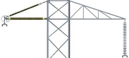
The CICA (Figure 1) can be used in both new and existing overhead transmission line projects. The traditional steel cross-arm and insulator strings increase both vertical overhang (suspension insulator) and horizontal swing (cross arm). The Double-V CICA allows for compaction where its single integrated modular assembly (Figure 2) reduces both vertical length and horizontal swing.
 |
|
2. This image provides a comparison of the Double-V CICA to a traditional steel cross arm configuration. Courtesy: SHEMAR Power |
Double-V CICA Overview
The Double-V assembly replaces the two-dimensional horizontal single Vee, a technology developed for compaction decades ago to optimize transmission tower geometry. However, with compaction, the single Vee still has limitations in bending stiffness and compression. Double-V has been found to provide like-for-like performance, with superior strength-to-weight ratio, elastic ability to withstand shock loads (such as during a broken conductor condition), and resilience against pollution-induced flashovers through the use of silicone rubber composite insulators making them the most suitable choice for insulated cross arms.
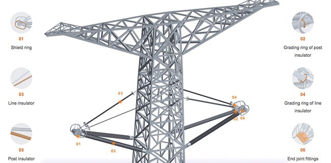
The Double-V CICA is a combination of composite line post insulators and suspension insulators, as shown in Figure 3. The composite line post insulator functions as a support for compression and bending loads while the suspension insulator functions as a support for vertical/tension loads.
 |
|
3. The elements of the Double-V CICA are detailed in this illustration. Courtesy: SHEMAR Power |
In addition to these insulator elements, the CICA also features the high-voltage (HV) end metallic connection node, conductor fitting components, tower side connection hardware, and electric field grading devices, all while eliminating overhang length and horizontal swing common with conventional suspension insulator strings. The Double-V CICA is one design type from the CICA family, a group that also includes the fixed/pivoting braced line-post, tetrahedron, and tripod.
The type of CICA design is decided upon after analyzing operating/loading conditions, and environmental conditions. The elements of the Double-V CICA are similar to the remaining CICA family, and cover the majority of transmission lines (<765 kV) in use in the U.S.
Solving Technical Challenges
Whether considering greenfield/new build, voltage/current uprating, and/or solving ground clearance issues, the Double-V CICA should be considered as a solution to these technical challenges. When applying a CICA solution in a greenfield/new build project, benefits to consider include:
- ■ Insulation Weight. Composite insulators have a significant impact on weight reduction compared to the conventional insulator. This weight reduction drives down costs associated with tower size and concrete needed for the tower pad. Not to forget reduction in labor and equipment utilization for the duration of the entire project.
- ■ Compaction. Since CICA can reduce phase-to-phase clearances and increase phase-to-ground clearances, the ease of right-of-way becomes of less concern while also lowering the visual impact of residential concerns with large structures. In addition, the overall electromagnetic field observed on the ground is reduced while surge impedance loading is increased.
For voltage/current uprating, consider:
- ■ Voltage Uprates. Replacing traditional cross arms with CICA while considering the re-use of towers/conductor, a voltage uprate can be realized as the necessary clearances from the insulator to tower structure and phase(s) to ground meet or exceed standard design requirements. For example, a 138 kV to 230 kV, or 230 kV to 345 kV uprate is possible.
- ■ Current Uprates. Since CICA increases the vertical distance between conductor and ground due to the elimination of the suspension insulator on conventional designs, the utility owner can effectively take advantage of the additional accommodation of wire sag. As noted earlier, the CICA is a combination of a composite line and suspension insulator, which, when designed accordingly, sees an increase in mechanical limits compared to the traditional cross arm design, allowing for an option to increase conductor sizes.
With regard to ground clearance, consider:
- ■ Ground Clearance. Similar to the benefits of current uprating, the traditional suspension insulator is eliminated, which effectively raises the conductor from ground. If the original wire sag is not increased (current or wire size is not adjusted), then an increase from the conductor to the ground will take place. This increase (radial and axial) can also provide benefit during special circumstances such as fire/vegetation mitigation, and clearance to bodies of water.
Consider the application of the Double-V Composite Insulated Cross Arm as a novel approach for overhead transmission line engineers, and U.S. grid operators, to solve current and future engineering challenges associated with the year-over-year load growth on the power grid, and issues related to the interconnection of new generation sources such as wind and solar.
—Favad Janjua (Favad.Janjua@SMARepcna.com) is director of Sales at SHEMAR Power USA.