When heat exchanger tubes—sometimes numbering a thousand or more per unit—begin to crack or wear, the effects can lead to a cascade of subsequent failures in adjacent tubes. If too many tubes are plugged, heat exchanger effectiveness is compromised, and power generation may be curtailed. If conventional mechanical plugs are used, they can break loose, leak, and fail. At that point, the replacement of a very costly heat exchanger is imminent.
However, if the latest sleeve installation technologies and techniques are used, the results can be lower materials and installation costs plus improved heat exchanger performance, without the need to take generation units offline while completing repairs. Perhaps most importantly, the sleeved heat exchanger can operate reliably for many years, saving the operator’s capital until a planned rebuilding or a replacement unit is installed.
Impending Death of Feedwater Outlet Tubes
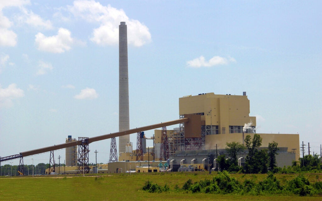
At American Electric Power’s (AEP’s) 995-MW Tanner’s Creek station, located on the Ohio River near Lawrenceburg, Ind., thermal stress cracking and wall loss in fall 2009 indicated impending failures of 60% of the feedwater outlet tubes in the heat exchanger on the plant’s 500-MW supercritical Unit 4.
“We had done some testing and were hopeful that the heater could be repaired,” explains Jay King, process supervisor. “It was not feasible to replace the heaters at that time. We had to have a certain amount of time to put together a replacement package to present to the board and show that it was justifiable to replace the heaters in the future.”
“We were at the point where we had to discuss abandoning the heaters until we could replace them. Unfortunately, this would possibly cut down our output because it would not be desirable to operate the heater in each string. This would greatly accelerate the end life of these heaters. To operate without any heaters in service would have meant as much as a 50-MW curtailment,” King adds.
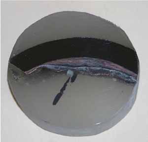
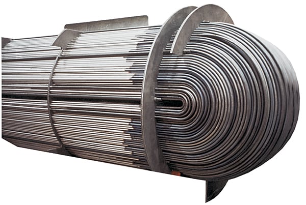
The two high-pressure feedwater heaters were eddy current–tested and found to have severe stress cracks from the back face of the tube sheet in the desuperheating zone extending approximately 6 feet to the back of the zone (Figure 1).
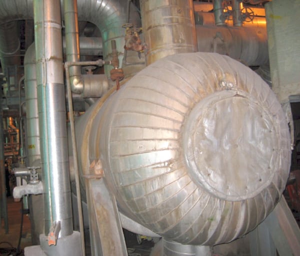 |
| 1. Test the heater. The pressure feedwater heaters were tested and found to have severe stress cracks from the back face of the tube sheet in the desuperheating zone extending approximately 6 feet to the back of the zone. Courtesy: American Power Services |
In order to verify the severity of the stress cracking, a tube sample was taken for laboratory analysis that proved the eddy current test was accurate. It would have been extremely difficult, if not impossible, to cut and pull a tube sample from these heaters via conventional methods due to the very heavy tube wall thicknesses. However, American Power Services (APS) was able to extract a tube sample using its advanced plasma arc tube cutter (PATC). APS’s PATC enables the cutting of heavy wall tubes at any length up to the tangent point of the U-bend in order to facilitate tube sample removal. Because the thickness of the tube walls ranged between 0.083 inch and 0.115 inch, cutting and removing (or even accessing) a tube sample would be very tough otherwise (Figure 2).
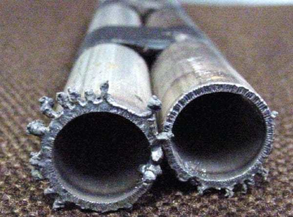 |
| 2. Remove the heater. American Power Services (APS) was able to extract a tube sample using its proprietary and patented advanced plasma arc tube cutter (PATC). APS’s PATC enables heavy wall tubes to be cut at any length up to the tangent point of the U-bend to facilitate tube sample removal. Courtesy: American Power Services |
“They came up with the idea of sleeving the outlet tubes to increase the longevity of the heaters and return the heaters to service,” says King. “They sleeved all the feedwater outlet tubes that had 70% or greater wall loss and had signs of stress cracking.”
Advanced Sleeving Revives Tubes
“At Tanner’s Creek the tube defects were roughly up to 6 feet back behind the tube sheet,” says APS Sales and Services Engineer David Grimes. “Instead of plugging the problem tubes, we went in with sleeves that were roughly 7 feet long and installed the sleeves in the inside diameter [ID] of the tubes and the sleeves extended past the area where the stress cracking or excessive wall loss was located. So, if the tubes continued to weaken and fail, then we have those liners installed that should prevent the tubes with through wall cracks from leaking.”
In installing the sleeves, APS employed an advanced hydraulic expansion method that utilized a flexible hydraulic expansion mandrel (Figure 3). The use of a hydraulic expander provides more uniform expansion and superior contact of the sleeve outside diameter with the ID of the parent tube. Additionally, the sleeves were strength-welded to the parent tubes at the face of the outlet tubesheet.
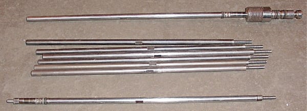 |
| 3. Sleeve the heater tubes. Instead of plugging the tubes, APS went in with sleeves that were roughly 7 feet long and installed in the tube inside diameter. The sleeves extended past the area where the stress cracking or excessive wall loss was located. Courtesy: American Power Services |
Grimes adds that with projects that utilize the advanced tube testing and sleeving technologies, there are benefits that are somewhat immeasurable. “In most cases, sleeving can be performed with the heater isolated while the unit remains online, which allows the utility to continue to generate electricity.”
Grimes notes that APS recommended installing the sleeves because plugging such a large percentage of tubes would have led to reduced thermal performance and increased feedwater velocity in the inlet of the unplugged tubes. Additionally, the plant may have had to cut a bypass orifice in the pass partition plate in order to prevent higher tube inlet velocities that would have led to further heat transfer degradation.
“I would say that, using this technology, our customers can realize savings of over 80% of the cost of a new heat exchanger if they elect to install sleeves rather than replace their problem heat exchangers,” says Grimes. After the sleeving project at Tanner’s Creek unit was finished, Jay King was surprised to see that heater performance was substantially maintained (Figure 4).
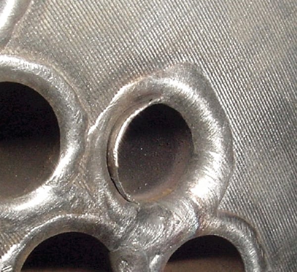 |
| 4. Weld the tube ends. The hydraulic expander provides more uniform expansion and superior contact of the sleeve outside diameter with the inside diameter of the parent tube. Additionally, the sleeves were welded to the parent tubes at the face of the outlet tubesheet for added strength. Courtesy: American Power Services |
“We would have expected to see a slight performance decay, since you have the sleeves in place in the desuperheating zone, because it’s now a heavier-walled tube,” he says. “But that didn’t happen. We maintained the same performance levels. The TTD [terminal temperature difference] and the saturation temperature of the heater (based on the pressure) versus the feedwater outlet, have not decayed at all.” Quite possibly that resulted from the selective, limited use of sleeving.
“The thing I liked best about going this route is that we didn’t have to abandon the heaters,” adds King. “That would have presented us with a very difficult situation on how we would start and shut down the unit without some serious pipe modifications and major changes in operating procedures. These heaters are used during start-up and are equipped with alternate drains that drain back to the condenser that must be utilized during start-up. The piping modifications would have meant a large added O&M expense and time lost for engineering to assess needed operational changes. The installation of the sleeves allowed us to maintain efficiency and return the unit to service maintaining a design basis.”
—Contributed by American Power Services.