The air preheater is a critical, yet often overlooked, component of the boiler combustion air system. Evaluating and optimizing a heater’s performance is difficult given how entwined it is with the entire combustion system and the lack of standardized calculation tools. Reducing leakage by using modern seal technology will improve combustion efficiency, maintain fan performance, and keep your downstream air quality control equipment operating within spec.
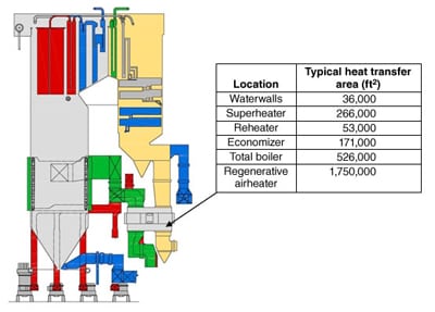
The regenerative air heater or air preheater (APH) on a large utility boiler often accounts for about 10% of the unit’s thermal efficiency. Its performance is so critical that just a 10F change in gas exit temperature can change the boiler efficiency by a quarter of a percent, representing hundreds of thousands of dollars per year in purchased fuel cost. For an aging fleet of boilers operating with ultra-low-NOx firing equipment, accurate measurement, control, and containment of the air and flue gas flowing through the APH is critical.
The major advantage of using an APH is that it is the least expensive heat-recovery device available that is capable of operating in the harsh environment of a fossil-fueled boiler’s flue gas exhaust. A major drawback of the regenerative APH is the undesired leakages that are inherent to its design.
Air leakage has the largest single effect on APH performance. Ignore the health of your APH long enough and you’ll soon experience some combination of corrosion, fouling, ammonium bisulfate plugging, increased auxiliary power consumption, and higher-pressure differentials that can limit combustion air fan operation.
On balanced-draft boilers, additional air in-leakage upstream of the APH from leaky penthouses, casings, and expansion joints quickly makes accurate control of excess oxygen problematic. Also, both APH leakage and upstream air in-leakage degrade air pollution control equipment performance by increasing the velocity of suspended fly ash and reducing electrostatic precipitator residence time. (See “Real-Time Monitoring System Measures Air In-Leakage,” August 2010 and “Air Heater Leakage: Worse Than You Think,” April 2006 in our archives at https://www.powermag.com.)
APH Design Fundamentals
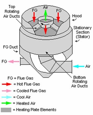
A typical APH is illustrated in Figure 1. A regenerative air heater captures the heat in boiler exhaust gases by passing them over a heat-absorbing metallic element. In this most common design of a regenerative APH (Ljungström) the element is continually rotated so that it alternately contacts the hot gases (red arrow) and the cool inlet air (blue arrow) produced by the plant’s forced-draft (FD) fans. Typically, about 50% to 60% of the total heat content of the exit gases is captured and recycled, resulting in about a 10% improvement in boiler efficiency when compared to an identical unit without an APH.
Also shown on Figure 1 are the various leakage paths through the APH. Each leakage type is discussed in detail below.
 |
| 1. Circumferential leakage through an APH. The left blue line represents the bypass seal leakage around the air preheater into the warm airflow. The bottom blue line represents the bypass seal leakage (also called peripheral seals) passing the axial seals into the gas path. The red line on the right represents the bypass seal leakage passing around the air preheater (APH) into the cold gas flow. The top yellow arrows represent the hot radial seal leakage, while the bottom yellow arrows represent the cold radial seal leakage. Courtesy: Storm Technologies Inc. |
Sealing these dynamic structures is extremely difficult due to their large diameter (up to 60 feet across) and the large temperature difference between their hot and cold ends (about 400F). Together, these characteristics produce significant radial thermal expansion difference between the hot and cold sides of the APH’s rotor after unit start-up. It’s not uncommon for the outer edges of a large APH at operating temperature to droop or “turn down” by 3 inches or more compared with the cold condition (Figure 2).
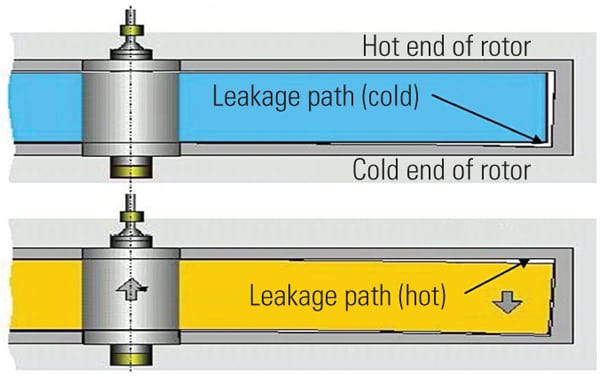 |
| 2. Thermal turndown. The typical APH may be as much as 60 feet in diameter. When the APH rotor is heated from a cold condition (blue), thermal expansion (yellow) can cause the rotor to droop or “turn down” up to 3 inches on the periphery. Knowing the amount of turndown is important when presetting the seal position before operation, because seal positions will change as the rotor warms to its operating temperature. Source: Storm Technologies Inc. |
This thermal distortion droop opens gaps in the sealing surfaces that separate the cold incoming air from the outlet gases as well as in the sealing surfaces around the circumference of the APH. Turndown changes the gaps between both the radial and circumferential seals and their respective sealing surfaces where gas and air bypass the rotor and heat exchange elements.
Two Types of Seal Leakage
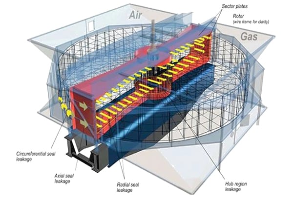
Consider APH leakage as being one of two types and taking one or more of four distinct leakage paths through regenerative APH seals (Paths A, B, C, and D in Figure 3). Each leakage path affects the economic operation and heat rate of the plant in a different way:
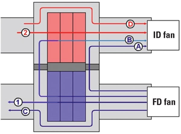 |
| 3. Four leakage paths through an APH. Path 1 is the normal airflow path through the APH and Path 2 is the normal flue gas flow path. Path A shows the forced draft (FD) fan flow leaking ambient air directly to the gas outlet duct (through the radial or circumferential seals). Path B shows preheated FD fan airflow that short-circuits back to the gas outlet duct. Path C represents ambient FD fan air that leaks around the APH and enters the boiler unheated. Path D represents hot flue gas exiting the boiler, bypassing the APH, and exhausting at a high temperature. Source: Storm Technologies Inc. |
- Circumferential/bypass leakage (Paths C and D) has an effect on heat transfer and boiler heat rate. A portion of the leakage Path C will also travel around the outside circumference of the rotor, joining the flow of leakage Path A and increasing fan horsepower requirements.
- Radial seal leakage (Paths A and B) is typically calculated as a percentage of the boiler exit gas flow (Path 2), not as a percentage of fan input airflow (Path 1).
Knowing the gas flow leakage (as a percentage) is convenient when calculating the “correction” in gas exit temperature that results from air in-leakage when doing overall boiler efficiency tests.
Circumferential Seal Leaks. Circumferential seals are located on the entire circumference of the APH rotor, on both the hot end and cold end of the APH. On the flue gas side of the APH, all of the leakage through the inlet side circumferential seals will short-circuit around the APH (bypassing the heat transfer element) and exit through the downstream circumferential seals. This leakage results in a loss of enthalpy transfer into the element and increases the temperature (and therefore the actual volume) of gas entering the induced-draft (ID) fans.
On the air side of the APH, the volume of leakage through the first set of circumferential seals will enter the annulus around the perimeter of the rotor, where the leakage will split in two directions. The volume of leakage in each direction depends on the differential pressures between points of exit. A portion of the flow will continue in a straight path and exit through the second set of circumferential seals. The remainder of the flow will be directed around the perimeter of the rotor and exit into the exhaust gas stream (through the axial seals), and that volume will, in turn, exit the APH through the gas-side cold end circumferential seals.
Most difficult to account for is air or gas bypassing the APH around the circumference of the APH. There is no simple or effective way to take an actual measurement of leakage around the circumference of the APH. These leakage rates must be calculated using pressure differentials and measuring gaps between the rotor and the circumferential/bypass seals, with an allowance for structural deformation at operating temperature, including rotor expansion and chord distortion between diaphragms.
One simple estimating approach is to consider the total leakage cross section as equivalent to that of a flat plate orifice to calculate the leakage flow rate. Although it is not a perfect match to perimeter leakage in an APH, it provides a closer approximation than traditional crack flow equations for ventilation systems, which are more appropriate for very small openings with very small differential pressures.
Radial Seal Leaks. Radial seal leakage represents the percentage increase in outlet gas flow caused by the mass of inlet air leaking into the gas outlet stream. (The majority of this leakage, as measured, is flowing past the radial seal area, but in reality, this measurement also includes other leakage paths, including entrained leakage and axial seal leakage.) Shockingly, leakage rates attributed to radial seals have been measured at over 40% in some APHs, and leakage rates around 20% are often accepted as a “normal” condition. However, this much leakage places a significant extra burden on the boiler fans in order to move gas and air that serves no useful purpose.
In addition, changes in fuels and operating conditions over the years often push ID fans to near rated capacity. When a fan is operating at over 80% of capacity, the slope of the horsepower/volume curve becomes very steep. At near full capacity, a 1% increase in fan volume often results in a 3% increase in required fan horsepower.
Two Radial Leakage Penalties
Two penalties to boiler performance occur with excessive radial seal leakage. The first is the thermal losses associated with the leakage air cooling the APH. The second is the additional auxiliary horsepower consumed by the fans for pushing more flow.
The first step in determining the thermal loss is to establish the gas outlet temperature corrected for no leakage. The ASME performance test code (PTC) assumes that all of the air in-leakage occurs on the cold side. However, in reality it is a mix of the hot and cold side radial leakage. The hot side radial leakage does not cool the outlet temperature as much as the cold side leakage does. Though the exact split will vary and can’t be directly measured, a good assumption is that the leakage is biased 60/40 to the cold side due to higher differential pressures and the higher density of cooler air at the cold end of the APH. Because the hot side radial seal leakage returns some of its heat to the cold air, use the gas outlet temperature instead of the air outlet temperature in your calculations.
Once a representative gas outlet temperature is calculated, the total enthalpy drop for the gas and the enthalpy rise for the air can be calculated to find the heat transfer efficiency. Dividing the enthalpy rise of the air by the enthalpy drop of the gas will give you the overall heat transfer efficiency for the APH.
The other impact that radial leakage has on plant efficiency is the increased air and gas flow through the fans. The flow and static pressures at a fan can be used to find the fan efficiency and, hence, the additional horsepower load placed on the fan(s).
Other Causes of Seal Leakages
Erosion caused by fly ash has resulted in the rapid loss of a heat exchange element as well as damage to perimeter seals, radial seals, and rotor diaphragms. The high ash content associated with many of the coals used at plants experiencing these problems is obviously a contributing factor. However, two other factors with regard to erosion are actually more important than ash content: abrasiveness and ash velocity.
The abrasiveness of fly ash increases as the amount of silica and alumina increases. In the case of some low-rank coals, the silica and alumina content of the ash can amount to about 90% of the total mineral content by weight.
Ash velocity is as much as three times more important than ash content or abrasiveness when it comes to determining the rate of erosion. One way to defeat high ash velocity is to increase the fineness of the coal particles leaving the pulverizers and balancing the coal and air flows to each of the burners.
Many combustion experts recommend a coal fineness of 75% through a 200-mesh screen to reduce the abrasive effects of ash in the furnace and downstream equipment (see “Finessing Fuel Fineness,” October 2008). Non-uniform flows can also cause high-velocity slipstreams that result in severe erosion of the outer basket rings (Figure 4). Also, pay careful attention to excessive turbulence of the flue gas entering the APH by adding flow straighteners and turning vanes as determined by computerized flow modeling studies.
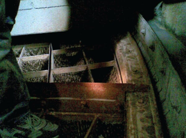 |
| 4. Typical erosion damage. The outer ring basket erosion shown was caused by fly ash abrasiveness and excessive particulate velocity. Courtesy: Paragon Airheater Technologies Inc. |
Cut Your Losses
The calculable savings for improving APH leakage are substantial. In addition, there are significant costs related to the impact that suboptimal airheater performance has on the combustion process and on FD and ID fans. Other impacts include erosion concerns downstream, precipitator performance issues due to higher inlet velocities (offset slightly due to decreased flue gas temperature), and other possible costs of colder combustion air, as discussed.
In some plants, just the fan horsepower wasted in handling radial seal leakage can exceed 3 MW, which can result in an overall net heat rate penalty in the range of 50 to 75 Btu/kWh—a 0.5% to 0.75% decrease in overall unit efficiency. On a typical 500-MW unit, this magnitude of radial seal leakage results in increased coal consumption in the range of 15,000 to 20,000 tons per year.
Research and modeling performed by Teodor Skiepko and Ramesh K. Shah (“Influence of Leakage Distribution on the Thermal Performance of a Rotary Regenerator,” Applied Thermal Engineering, Vol. 19, 1999 and “Modeling and Effect of Leakages on Heat Transfer Performance of Fixed Matrix Regenerators,” International Journal of Heat and Mass Transfer, Vol. 48, 2005) concluded that, in some cases, just 10% leakage can reduce the overall thermal efficiency of an APH by 9.8% to 13.2%, depending on the proportion of flow that goes through each leakage path. This is a very substantial decrease in performance that can be prevented.
To assess APH performance, the temperatures in and out of both sides of the APH need to be known as well as the oxygen concentrations before and after the gas side of the APH. Velocity heads need to be measured, where practicable, to determine if there are any significant flow stratifications in the ducts. If so, the temperature and oxygen should be averaged on a flow-weighted basis. Furthermore, to perform a proper thermal heat balance, the air and gas flows must be known before and after the APH. These temperatures can be calculated as a function of O2 levels, static pressure, temperature, and velocity head measured at the both entrances and exits of the APH.
Calculating the motor horsepower and understanding the heat rate impacts of the APH, system draft, and unit load is extremely important when conducting an evaluation of this system. For example, draft increases also affect fan power consumption. Total draft and flow impacts can be evaluated on a case-by-case basis provided the system leakage and static pressures have been measured along with design APH and fan data.
The ASME PTC 4.3 Air Heater Test Code is somewhat outdated and differs slightly from how a modern field test is conducted. The code suggests comparing the amount of carbon dioxide (CO2) before and after the APH instead of oxygen, which is much more easily measured. Unfortunately, not all of the possible leakage paths discussed above are identified by the code, and CO2 is typically a calculated value, not a measured one. The code also has no provision for air or gas bypassing the APH through the circumference of the APH. It only includes the effect of air that bypasses the APH and short-circuits to the flue gas flow.
Reducing APH Outlet Gas Temperature
To minimize fuel consumption, the flue gas exit temperature from an APH must be kept as low as practical. Go too low and the baskets and cold end structural elements will experience destructive acid condensation and therefore corrosion. However, compared with the cost of the excess fuel burned to maintain a gas outlet temperature well above the dew point to reduce cold end corrosion, the cost of a replacement set of cold end baskets is almost incidental.
The chemical process that causes the cold end acid corrosion is well understood. Acid condensation occurs wherever the gas temperature is reduced to less than the saturation pressure (partial pressure) of the SO3 present in the flue gas. Under those conditions, a dilute solution of sulfuric acid condenses on and is corrosive to APH structures and baskets. That is why, in most plants, the cold end element layer in an APH is sacrificial and is designed to be replaced relatively easily and at modest cost.
In modern power plants, operations strive to minimize gas outlet temperatures by maximizing APH heat transfer efficiency. There are two principal ways to decrease the exit gas temperature on an existing unit: increased element depth and APH speed of rotation.
Some of the APHs installed today were originally designed with some open space that can accommodate several inches to several feet depth of additional heat transfer surface area. Adding additional heat transfer surface will decrease the exit flue gas temperature. For those units without extra space, alternate basket designs are available that have the same outside depth as the original baskets, but they can accommodate up to 3 inches of additional element depth by modifying the traditionally deep structural bars at the top and bottom of each basket.
Most air heaters were designed to operate at a single, fixed speed of rotation. The recent studies by Skiepko and Shah indicate that it may be possible to increase the thermal efficiency of an existing air heater by changing its speed of rotation. The practical application of this concept is unproven, but preliminary full-scale experimentation at a plant in North Carolina has shown encouraging results.
Additionally, slowing the speed of rotation during air heater sootblowing operation can be used to increase the sootblower residence time in the faster-moving outer radius of the air heater, which can help maintain air heater cleanliness.
Leakage Repair Solutions
A cost-effective and simple method for reducing APH leakage is replacement of the original equipment gas seals with newer design high-performance, full-contact radial seals and self-reinforcing circumferential or bypass seals. Full-contact seals have a proven performance record in reducing APH leakage by as much as 50% when used to replace the original equipment type of radial seals commonly found today on most APHs.
An example of a high-performance, full-contact radial seal is shown in Figure 5. The full-contact DuraMax radial seal is constructed with a spring bellows that allows the seal to maintain continuous but flexible contact with the sealing plate at all times, effectively eliminating the main path for radial seal leakage. It is designed to maintain contact even when the mating sealing surfaces (sector plates) have become distorted or out of plane. In comparison, the original design seal was more of a rigid “proximity” air dam that is much less effective, especially with an aging air heater that has drifted from its as-new dimensional tolerances (Figure 6).
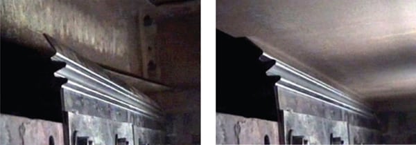 |
| 5. Seal of approval. The continuous-contact DuraMax seal is shown, before (left) and after (right) sector plate contact. The full-contact seal is constructed with a spring bellows that allows the seal to maintain a continuous but flexible contact with the sealing plate at all times, effectively eliminating the main path for radial seal leakage. Courtesy: Paragon Airheater Technologies Inc. |
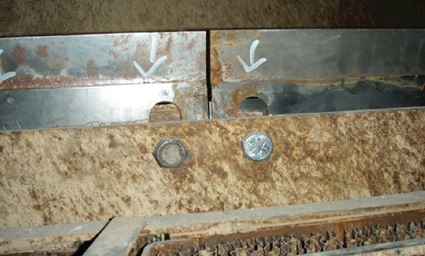 |
| 6. Original recipe. The original style of radial seal was more of an air dam rather than a seal. Courtesy: Paragon Airheater Technologies Inc. |
The new DuraFlex circumferential seals have an interlocking and self-reinforcing structural design that allows them to be set in close proximity to the rotor sealing surface without being damaged, thus minimizing gaps and leakage openings (Figure 7). The original style seals that this design replaces are shown in Figure 8.
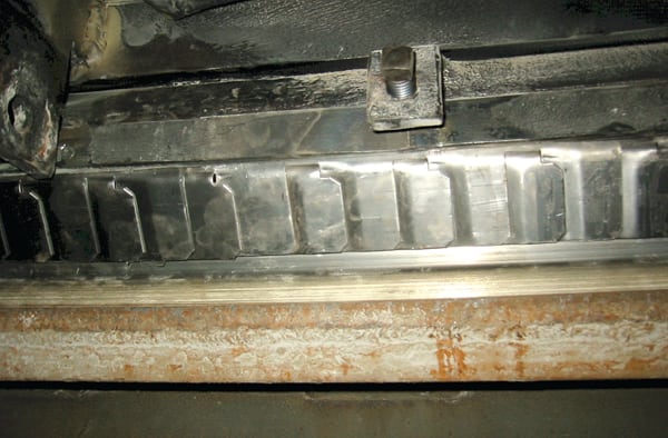 |
| 7. Sealed tight. The DuraFlex circumferential/bypass seal has an interlocking and self-reinforcing structural design that allows the seals to be set in close proximity to the rotor sealing surface to minimize leakage. Courtesy: Paragon Airheater Technologies Inc. |
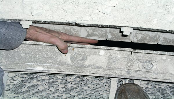 |
| 8. Old seal technology. The original circumferential/bypass seal design can be easily damaged if it makes contact during operation, and it may often be set with an excess gap to reduce the potential for damage, but with resulting increased leakage. Courtesy: Paragon Airheater Technologies Inc. |
An example illustrates the positive benefit of APH leakage reduction when replacing standard, rigid seals with full-contact radial seals to reduce just radial seal leakage. After replacement with full-contact DuraMax seals at American Electric Power’s 500-MW Welch Station Unit 3, the ID fan amperage decreased by over 23%. The motor amperage is directly proportional to the motor power requirements (see table).
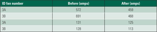 |
| Seal the deal. Test results from AEP’s Welch Station Unit 3 found a 23% reduction in induced draft fan amps with full-contact radial seals when compared with the original style of circumferential seals. Source: Storm Technologies Inc. |
— Stephen K. Storm (stephen.storm@stormeng.com) is executive vice president, technical field services at Storm Technologies Inc. John Guffre (jguffre@paragonairheater.com) is chief research scientist for Paragon Airheater Technologies.