J-seals are an integral part of efficient steam turbine operation. The failure of a J-seal can cause significant damage to the turbine rotor as material migrates downstream. For that reason, plant staff should be aware of the type of sealing technology installed in their equipment and understand how best to conduct inspections of their steam path systems to identify potential problems during regularly scheduled outages.
Steam turbine efficiency relies heavily on the integrity and performance of the steam path stage-to-stage seals. Sealing among the rotating turbine components, stationary nozzles, and casing is established by using a labyrinth of high-to-low seal tooth interfaces.
The tight tolerance labyrinth is designed to generate a pressure drop across each seal tooth, ensuring only a small amount of steam passes relative to total turbine steam flow. Replaceable J-seals are a common inter-stage sealing technology used by steam turbine original equipment manufacturers (OEMs). By replacing worn J-seals, the owner can re-establish state-to-stage sealing efficiency during major steam path overhauls.
Inspection Tips
J-seals are a two-piece design and manually assembled, which increases the risk of installation error by the installing technician. If the seal is not installed correctly, the caulking wire will distort and hump under thermal stresses, and could liberate from the groove. Once the retaining material loosens, the seal is at risk of failure. Liberated seal material can migrate downstream through a rotating steam path, causing significant damage.
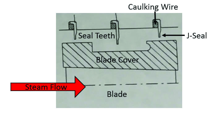
It’s important to know the type of sealing technology used in the steam path prior to any unit inspection. Blade plans for each section of the rotor should be reviewed to verify the sealing type used (Figure 1), position of the seal teeth, the direction of steam flow, and any other details.
 |
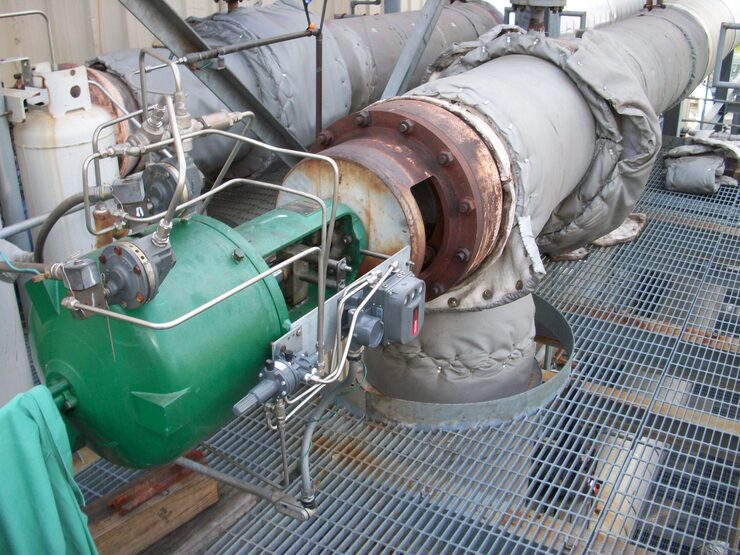
| 1. Inspection planning is key. J-seals are a common inter-stage sealing technology used in steam turbines, and are designed to be replaceable, so turbine operators can re-establish stage-to-stage sealing efficiency during steam path overhauls. Blade plans should be reviewed and technicians should know the sealing technology used in the steam path, making it easier to spot J-seal problems. Courtesy: HRST |
In order to protect the steam path from liberation- and migration-induced damage, biannual borescope inspections are recommended to verify the health of the seals. The borescope inspector should focus efforts on the rotating blade cover to stationary casing interface at the top of the blade to discover loose and liberating J-seals. Any seal suspected of liberation should be inspected 360 degrees around the stage to find any breaks in the material.
The Case of the Liberated J-seals
A large high-pressure (HP)/intermediate-pressure (IP), dual-flow low-pressure (LP) steam turbine user was preparing for a shutdown to perform an annual borescope inspection. The unit had abnormally high vibrations and load-bearing issues at full baseload. An operations analysis highlighted the likelihood of internal damage due to load-bearing issues; misalignment was also a factor, requiring more information to diagnose damage.
During the planned outage, the unit rested quickly after the turning gear failed to engage. The unit cooled while stationary as the rotor could not be turned manually. Help was needed to diagnose turning gear and unit-turning issues. Attempts to roll the rotor failed; something internal to the steam path was preventing the rotor from performing as designed.
One potential culprit was failed J-seals. The fact that the rotor wouldn’t turn was an indication that material may have migrated downstream, and at this point, plans were made to inspect the downstream steam path for damage. In this case, there was concern that broken J-seal material may have traveled into the LP system.
Casing drawings of the unit identified the location of four borescope inspection ports. The first port was opened and provided access to the last stage IP exhaust to the LP inlet crossover pipe (Figure 2).
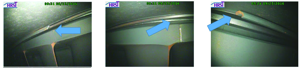 |
| 2. Spotting J-seal liberation. A borescope inspection provides images of J-seal liberation inside the turbine. Here, the arrows point to J-seal issues, with J-seal and caulking wire liberated from the casing groove, likely sending material downstream. Courtesy: HRST |
Liberation risks include reduced sealing efficiency, vibration from steam whirling instability, and potential hot spot rubs due to material balling. In the worst case, material migration can create substantial downstream steam path damage, and foreign material freely flowing through a steam path wreaks havoc on seal interfaces. Even the smallest material can lodge between mating seal faces, and be picked up by the rotating seal teeth, compromising the tolerance between rotating and non-rotating components and damaging the seal teeth.
The seal teeth grab the loose material and then swipe away the stationary seal face, creating a ball of seal material and a running high spot that picks up heat and causes vibration. In severe cases, the high spot impacts the rotor as it coasts down to the turning gear. As speed decreases, the ball of material cools, but if the rotor stops for any reason, the material in effect welds the stationary casing to the rotating blades, and the rotor locks up (Figure 3).
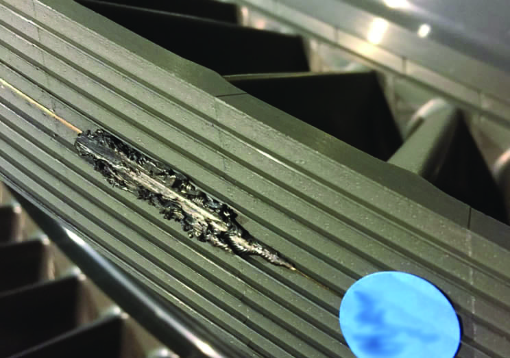 |
| 3. J-seal material can lock up a rotor. A ball of material swiped from the stationary seal face, such as that shown here, can weld itself to the blades and lock up the rotor, causing damage and necessitating repairs. Courtesy: HRST |
A detailed review of the system drawings (Figure 4) found a threaded pipe plug located at the LP steam piping elbow entering the LP system. Scaffolding was erected, insulation removed, and a borescope inserted into the crossover pipe elbow. This provided access to the LP steam path flow divider and first-stage LP nozzles.
 |
| 4. The steam path arrangement. A review of the system drawings for the steam path in this case located a strategically placed inspection plug that enabled a borescope inspection of the low-pressure (LP) steam path flow divider and first-stage LP nozzles. Courtesy: HRST |
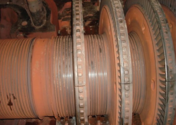
A J-seal caulking wire was discovered, lodged in the LP stage 1 nozzle (Figure 5). Due to the flow of the steam path, the material could only have come from upstream. This proved that the failed J-seals identified at the IP exhaust had migrated downstream and were very likely the cause of the locked rotor condition.
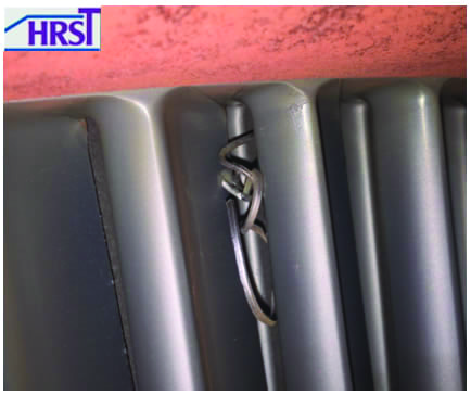 |
| 5. One of the culprits. A caulking wire that had migrated from upstream in the steam path was found in the LP stage 1 nozzle, providing more evidence of upstream J-seal failures. Courtesy: HRST |
After discovery of the migrated caulking wire, it was recommended that the LP crossover pipe be removed to provide manual access to the flow divider for closer inspection and material removal. The plant also decided to uncouple the HP/IP rotor from the LP rotor to verify which rotor was locked; the HP/IP rolled, the LP did not. Access to the LP flow divider and stage 1 nozzles allowed the borescope to proceed farther back in the LP steam path, and showed a migrated J-seal at the inlet of the stage 2 nozzle.
Open-casing Inspection
It was recommended the LP rotor be removed from the casing in order to fully inspect the steam path for damage and remove the liberated material.
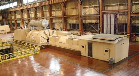
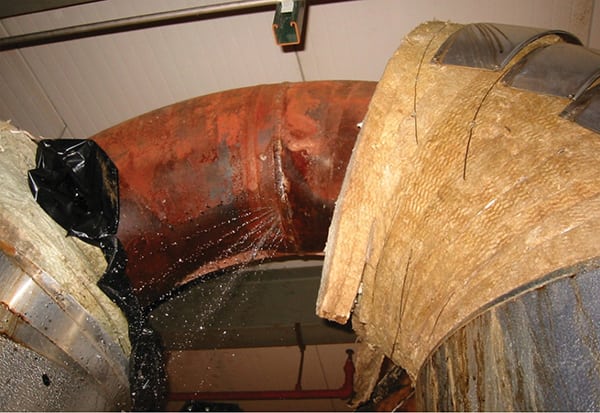
With the turbine open (Figure 6), an attempt was made to roll the unit with a brass bar placed through a coupling bolt hole. The rotor would not roll, so more force was applied using the overhead crane; the rotor rolled, but slowly. The rotor was clearly locked up on a high spot; the sound of metal scraping the casing was heard as the rotor turned. Once the high spot passed the casing split joint, the rotor rolled smoothly without noise.
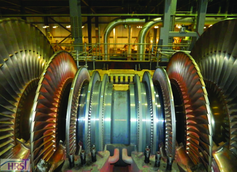 |
| 6. Looking inside the LP turbine. The LP rotor is shown here after the upper half of its casing was removed. Once open, the rotor was manually turned, which led to the determination that swiped J-seal material (shown in Figure 3) was responsible for the binding in this case. Courtesy: HRST |
The material shown in Figure 3 had welded itself to the casing, and was determined to be the swiped seal material responsible for binding the rotor. With proof that the migration of J-seal material into the steam path was creating restriction, the decision was made to open the HP/IP rotor to inspect for more J-seal damage.
The top half of the HP/IP casing was removed, and the stationary seals were inspected, which allowed for failure mapping and a closer look at failures across the system at each stage. The failure analysis did not point to a rub event as the cause of failure as the seal teeth were in good condition, with no signs of “mushroom” as would be expected during a rub.
Further inspection determined the caulking wire was backing out of the retaining groove at five stages. Based on the understanding of the installation process, it was determined the same operator likely installed all the seal sets that were failing. The customer’s insurance investigator reviewed the findings independently on-site without HRST’s involvement and came to the same conclusion.
A complete structural inspection of the steam path was conducted to look for any other suspected J-seal failures. Both the HP/IP and LP rotors were removed from the casing to allow access, and two inspectors were tasked with looking at hundreds of J-seals. The inspection included identification and removal of foreign material, visualization of all caulking wire and J-seals, and measurement of all caulking wire butt gaps and peened fits.
A failure in any area required the inspection team to mark the finding with a blue dot and inform engineering for a disposition. All foreign material also was marked.
Repair Process Controls
In this instance, engineering and disposition repairs were performed, controlled with operating procedures developed by HRST. Several factors that impact the quality of a J-seal repair must be controlled during the repair process. It is important to verify the qualifications of all installation technicians, and to verify that all materials used are in accordance with the OEM design specification. Peening gun anvil size and air pressure must be correct, and several critical measurements must be taken and confirmed to be within their proper tolerances.
Upon complete inspection of the required repairs, and with no other outstanding issues, the unit was released to the customer for installation. In this case, 16 seal sets were fully removed and replaced, four humping concerns were re-peened, two rotating stages required seal machining, and all seal teeth were sharpened prior to release to the customer.
However, the seal inspection and repair ended up as a relatively small piece of the overall repair scope. The customer was forced to send the rotor off-site to have it straightened due to the bowing that occurred when it could not be rotated as it cooled. MD&A in St. Louis performed the work via “hot shot” application, and returned the rotor run out to OEM specifications. ■
—Bryan Grant is a steam turbine reliability engineer, and the maintenance and repair planning manager for HRST Inc.