Wind turbine blades, gearboxes, and generators get most of the attention both within and beyond the power industry. The focus is often on increased capacity and blade lengths, as well as drive train premature failures. That’s natural, because those rotating blades are the most visible part of a wind project. However, successful operation of a wind installation also depends on attending to the many balance-of-plant components that are less visible.
Wind energy in the U.S. has grown rapidly over the past decade. From a 9,000-MW installed base in 2005, the industry expects nameplate capacity of nearly 80,000 MW in operation by the end of 2015. As this energy source is becoming increasingly prevalent across the grid, the integration and reliability of projects becomes even more critical.
What is seldom recognized is that these projects need to be viewed and managed as power plants, not just as individual turbines.
The Scale Challenge
In Europe, most wind turbines are clustered in small groupings of 10 or fewer and are positioned near the users—factory district or township—so long-distance transmission is less critical, and a single project is unlikely to have a major effect on grid stability. As wind energy projects become more widely scattered throughout the U.S., they, too, will be less likely to vary in output all at once and will create a much more stable energy source overall than when the industry was in its infancy. In fact, a recent National Renewable Energy Laboratory (NREL) study has shown that modern utility-scale wind turbines equipped with active power controls will actually add to grid stability by having the capability to adjust output based on demand in very small time frames.
In addition, modern turbines have excellent low-voltage ride-through capabilities as well as the ability to provide variable power factor correction to the grid. All in all, wind is quickly becoming a low-cost, reliable, and productive part of the energy system.
There’s a big difference in what we are doing in the U.S. and what has happened in Europe. Many U.S. wind projects may consist of multiple phases totaling well over 300 turbines, and some are much larger; there are proposed projects with as many as 800 turbines with peak capacity ratings of over 2,000 MW. Most turbines are connected in groups (strings) of 10 to 12, which are then collected into a main substation for distribution to the grid. Most project substations are designed to manage the output of 60 to 120 turbines and step up the collection system voltage (typically 34.5 kV) to the local transmission voltage and to provide the necessary protection and control components required by the North American Electric Reliability Corp. and Federal Energy Regulatory Commission (NERC and FERC) reliability standards.
In my view, it is critical for these main substations and the supporting turbines and collection system be viewed as a single power plant, with all of the complexity of design and maintenance programs expected at a traditional generation facility.
How a Wind Project Collects Energy from Turbines
The typical U.S. wind project phase, as mentioned, will have 100 or so turbines. Nearly all turbine generators/drives have a three-phase output voltage of 690 VAC. Some older machines utilize 575 VAC, and there are a few at 12 kV, but those are rare.
This voltage is then stepped up by either an internal generator step-up (GSU) transformer (typically dry-type) or an external pad mount liquid-insulated transformer. Again, the typical output voltage from these is 34.5 kV, but other voltages are sometimes utilized for the collection system.
Because wind projects can cover thousands of acres, the collection system wiring is very complex, with long runs and many connections. The reliability of these two balance-of-plant components, the transformers and the collection system wiring, have the greatest effect on the reliability of the power plant as a whole. A transformer or cable failure can often cause the entire string of turbines to go offline, depending on the location of the fault.
Compare that type of event to the failure of a gearbox or generator, which will only affect a single turbine and reduce the output of a large project by less than a single percent. That is still significant, but it has limited impact. Needless to say, the main GSU transformer at the substation is much more critical, but normally, they have a high enough profile that catastrophic failure is rare. Assuming that the substation is maintained as required by best practice and regulations, it is still important to focus testing and maintenance on the balance of the high-voltage system.
Maintenance Planning
Maintenance planning for the electrical equipment and systems begins at project inception, with considerations such as logistics, access, equipment configurations, and priorities based on long-term service data. Also important is the ease of isolation, implementation of safety devices, as well as removal and installation for component testing and maintenance.
According to both the National Fire Protection Association (NFPA) 70B Recommended Practice for Electrical Equipment Maintenance and the Canadian Standards Association (CSA) Z463 Guideline on Maintenance of Electrical Systems, it is critical to safety compliance that the equipment work properly when energized. This can only be confirmed by initial acceptance testing as well as periodic maintenance testing. Of course, establishing a solid baseline for trending analysis is also useful for preventative maintenance and predictive maintenance planning. Reliable performance, reduced maintenance costs, and a safer work environment are all drivers for competent and thorough acceptance and maintenance testing.
The manufacturer’s specifications and recommendations should always be followed, but the overall system performance is evaluated based on visual and mechanical inspections, electrical testing, and comparison with expected testing values. To that end, industry consensus standards have been developed to ensure proper consideration is given to this testing.
Since 1975, the InterNational Electrical Testing Association (NETA) has published Standards for Maintenance Testing for Electrical Power Equipment and Systems. It has also been approved as an American National Standards Institute (ANSI) standard. This and the manufacturer’s documentation help provide both the test methodologies and expected results for testing most types of electrical equipment and serve as the basis for a good testing plan. Additionally, NERC/FERC guidelines provide critical information for substation settings and reliability expectations. Experienced engineering support and well-trained technicians should be very familiar with these standard procedures and how to apply them to the unique requirements of a wind generation facility.
Transformers: Why and Where They Fail
With transformers, it is important to understand the various types and reliability issues regarding the two basic configurations: turbine internal dry-type and liquid-insulated pad-mount transformers.
One consideration with internal dry-type transformers, as they are often mounted in the nacelle, is that the long cables run to the base of the turbine are at high voltage. This makes for smaller conductors, lower amperage, and possible lower arc flash ratings. However, great care must be taken in the installation of the cables, and all of the testing of the transformer must be performed either from down tower or in a locked-out, de-energized state.
It can also be difficult to ensure proper cooling and ventilation, especially in hotter climates. This could lead to early deterioration of the cast coils and premature failure of the transformer. Unlike the liquid-insulated variety, it is not possible to perform field services to extend the life of a dry-type transformer, and a medium-sized crane is required for replacement.
The no-load core losses for dry-type transformers are often higher than for their liquid-insulated cousins, which can result in higher costs even when the turbine is not generating. Some studies done in Austria have shown that reducing these losses by utilizing optimized transformers can save the equivalent of 17 MWh for a typical 1.5-MW turbine. This energy is often purchased from the grid at a higher rate than the selling price for generated energy. That’s not really a maintenance issue, but it should be a consideration when choosing new or replacement equipment, as transformer design and material choices can improve these losses.
Wind energy applications for almost all project components are more rigorous than what might have been first thought. Transformer applications are a good example.
Most wind projects utilize pad mount liquid-insulated transformers, and the most common models that have been installed do have their shortcomings. Many are actually designed and rated as distribution transformers rather than generator step-up units, and that has created a high level of early failures. Some reports show that some of these transformers may only average three to five years under these strenuous conditions. Distribution applications, which commonly step down the voltage for end use, assume a relatively constant load on both the high- and low-voltage sides and a clean, sinusoidal waveform.
The energy generated by the wind turbine is almost always disruptive in several ways. Wind turbines often cut in and out several times a day, except in ideal wind conditions, based on both minimum and, unintuitively, maximum wind speed. This erratic load level can create multiple in-rush currents and, more importantly, thermal cycling beyond the design of the transformer. The resulting expansion and contraction of components has been shown to have a direct effect on the life of fuses, winding wires, and other metallic parts, including insulated bushings. This thermal cycling can also lead to the loosening of connections, both internal and external, which can result in arcing, insulation deterioration, and lead failures.
Ground faults in the collection system cables can also be very detrimental to the transformers; therefore, surge arresters and special grounding transformers should be utilized in the system to help alleviate some of these destructive conditions.
Many wind turbines now utilize a fully converted AC/DC–DC/AC output, allowing for variable speed generation with constant voltage and frequency supplied to the transformer. These electronic components normally deliver less-than-ideal waveforms that can be very destructive to the transformer if it is not designed to manage those waveforms. In some turbine designs, there are filtering circuits to smooth out the waveform, but these are often not monitored, and a failure mode defaults to bypassing the filter.
Both the generator and the convertor can create harmonics and other distortions at every cycle, which lead to overheating and eddy currents in the windings, again shortening the life of the insulation. Low-voltage ride-through events also contribute to thermal stress on all of the components. Switching events from circuit breakers on both the low- and high-voltage side of the transformers can also create surges and transient overvoltages. Lightning strikes anywhere on the system can, of course, create overvoltage conditions as well.
Another consideration is the sizing of the transformers. Often, during the development phase of a wind project, the cost/value of transformers can be under-calculated, leading to a smaller transformer than what is ideal. It has been suggested that the transformer be sized at least 15% above the nameplate rating of the turbine to account for overspeed production as well as voltage variations. This would mean that a typical 1.5-MW turbine would probably need at least a 1.65 kVA rating, but that would be an unusual size. In most standard product lines, the size jumps to 2 kVA, so it has only been since all of these issues have come to light that the specific designs and sizes needed for wind turbines have become readily available. That being said, lead times are still often long, and remanufacturing companies probably have difficulty sourcing the properly sized cores to rebuild.
Most wind projects do have programs to sample and analyze oil from their transformers (Figure 1). Generally speaking, most of the failures that have been discussed are not due to moisture or other general degradation of the insulation but to arcing and other events that can create explosive gasses (typically hydrogen and acetylene) that are both dangerous and destructive. Most failures are contained within the transformer housing, but there have been cases of fires and explosions.
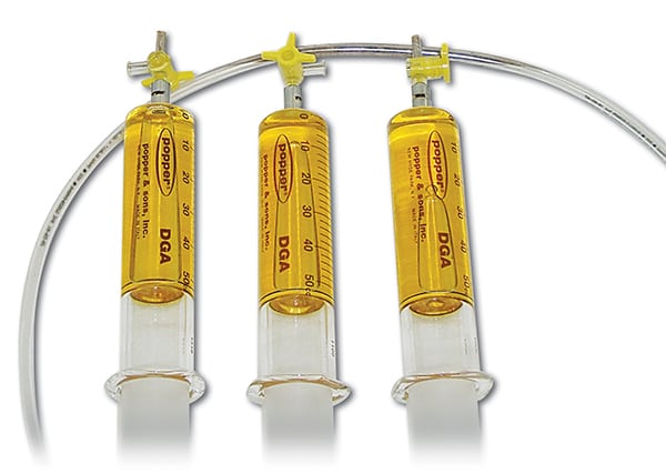 |
| 1 Even wind power requires oil. These typical dissolved gas analysis syringes are used to collect insulating oil from pad-mount transformers. The oil should be tested periodically for predictive maintenance. Courtesy: Shermco Industries |
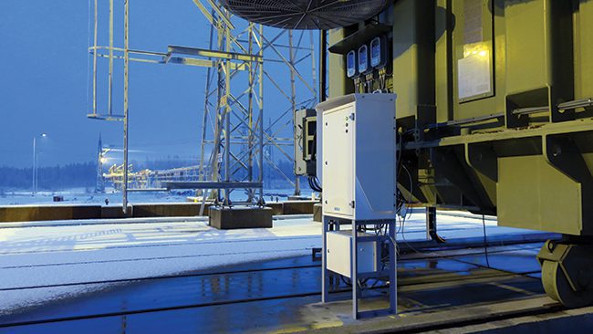
Employee safety should be the most critical factor in making decisions regarding the safe condition of a transformer. At-risk transformers can be especially dangerous when the low-voltage side of the cabinet is opened while energized for switching (Figure 2). Many new transformer designs, as well as after-market upgrades, are available with the various gauges and sample ports located outside of the enclosure. This allows sampling and monitoring to be done more safely and without de-energizing the transformer.
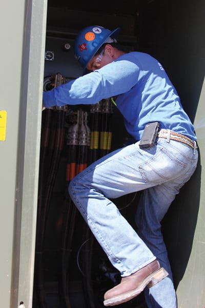 |
| 2. Safety first. Tight transformer enclosures can make it difficult to take good samples, even when they are de-energized. External valves and gauges can improve safety and ease of sampling. Courtesy: Shermco Industries |
Speaking of switching, it is very common for these “strings” of transformers to be daisy-chained to allow for ease of construction. Normally, no switchgear is utilized in making the connections. A transformer internal load break switch is used to de-energize the turbine for service while leaving the daisy chain intact for the balance of the “string.” This is not the primary purpose of the switch, of course, and the repeated use can result in both destructive surge electrical conditions and premature mechanical wear. It is also not always a safe way to disconnect a turbine, but it is probably considered cost-efficient.
There have been many improvements and suggested upgrades to help with these transformer issues. Electrostatic shielding between the primary and secondary windings has been strongly recommended by several manufacturers, as has an increase in the level of insulation within the coil structure. Alternative insulation system designs have been proposed utilizing more robust and thermally upgraded materials such as aramid papers instead of the typical cellulose-based materials. Also, the use of silicone or synthetic ester oils seems to be becoming more popular for some applications. These designs, in theory, could be safely installed inside the turbine, as they offer a greatly reduced fire hazard.
External switchgear for control of the collector system could also isolate or alleviate some of the damaging operations. There are also newer transformer designs with automated monitoring of moisture content, dissolved hydrogen gas levels, and thermal data from the actual windings utilizing fiber optics. Expensive? Probably, but the options are there.
Collection System Cables and Connections: Hidden Assets
Most wind projects have miles of directly buried high-voltage cables. These are often terminated and spliced underground, where faults are difficult to locate and repair.
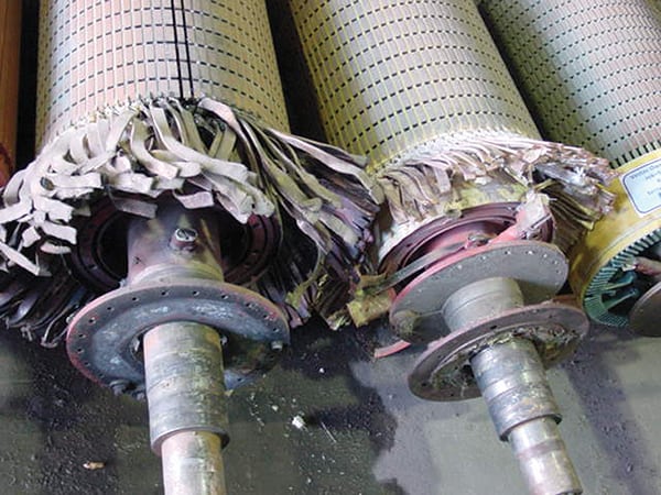
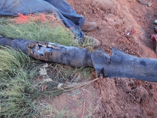
Again, due to multiple factors—including load cycling, environmental conditions, poor installation, and ineffectual acceptance testing—these cables are often bad actors at many projects. The good news is that the cables themselves are rarely the problem; most of the failures (as shown in the opening photo and Figure 3) occur at terminations and splices, and several testing procedures are well known that can facilitate the repair of these cables.
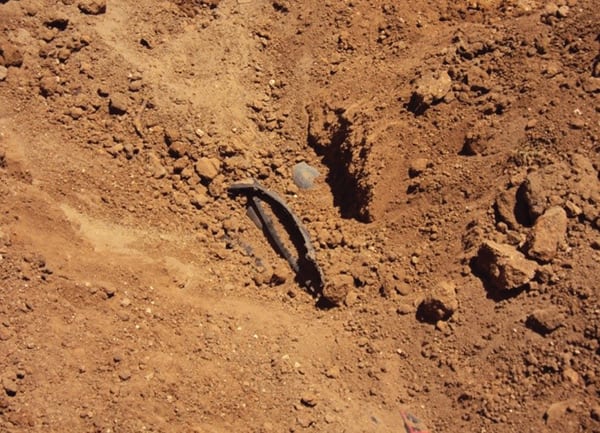 |
| 3. Failed splice. Splice and termination faults are very common in buried cables. These are commonly identified and located using one of several methods, including very low frequency, high-potential and partial discharge testing. Courtesy: Shermco Industries |
Online partial discharge testing as well as very low frequency potential tests are common. In many difficult cases, or at sites with chronic problems, off-line partial discharge testing is probably the best idea. Regardless of the methodology, these technologies have been developed and proven for many years in industrial and utility applications.
Because many wind projects are located in rough terrain and harsh conditions, there can be damage due to thermal cycling, soil expansion/contraction, and difficult installation sites. It has been suggested that installing splices and other connections in above-ground enclosures would be very conducive to reducing the cost of cable inspection, maintenance, and fault location. The installation would be easier and cleaner for the original construction team and, with most faults occurring due to improper installation, it makes sense.
Substations: Special Circumstances
Main substations are mostly trouble-free, with only the typical problems experienced by any other step-up substation installation. Of course, they must be tested during scheduled outages to maintain NERC/FERC reliability requirements, but strange things do happen.
For example, there have been cases where the large GSU transformer foundation was inadequate and the transformer partially sank into the sand.
And snakes. Don’t forget about snakes. Most wind technicians are not trained to work inside the substation fence, so some general maintenance could be overlooked. Don’t let that happen. Losing the substation transformer or supporting systems will take down the entire project.
Commitment to Proper Maintenance Matters
Wind projects are large, complicated, and often understaffed, but the proper operation and reliability of electrical equipment and associated protective devices is directly related to the quality of equipment maintenance. Following a systematic inspection, a good maintenance and testing program will protect the investment in equipment and enhance the production capability of the project. Executing maintenance tasks flawlessly is good, but that alone is not enough. It is critical that good maintenance priorities are implemented for both reliability and worker safety.
Planned outages are crucial for regulatory compliance, but they are also very important in maintaining the reliability of a project. They should be carefully coordinated between production, maintenance, and any third-party contractors to minimize disruption of the asset’s availability and to make sure that all aspects of reliability and safety are considered before the event. Infrared inspections, oil samples, and visual inspections should all be done in advance so that all replacement components and parts are available before the outage. Transformers are much easier to change or upgrade during an outage when the project is offline and the cost of the replacement component can be managed without rush deliveries and overtime services.
As the wind energy industry matures, more traditional reliability programs are being implemented. The resultant efficiencies in production and maintenance, as well as enhanced worker safety, will continue to improve the overall profitability of wind projects and reduce the effective cost of wind energy production. Wind offers a stable cost hedge against the vagaries of fossil fuel pricing and is proving that it can be as dependable and available as other sources of energy. This will only improve as new technologies and methods are introduced. ■
— Kevin Alewine (kalewine@shermco.com), corporate director of marketing for Shermco Industries, previously served as director of the company’s renewable energy services and for 35 years has focused on the manufacture and repair of rotating machinery up to 15 kV. He is active on several IEEE Dielectrics and Electrical Insulation Society testing standards working groups and is chair of the American Wind Energy Association O&M Working Group.