COMBINED-CYCLE RELIABILTY
Why bypass desuperheaters fail
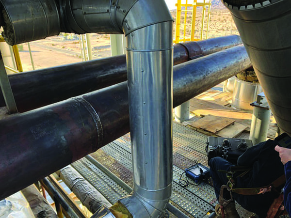
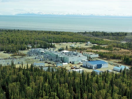
Over the past few years, Thielsch Engineering has been retained several times to inspect, evaluate, and/or repair a through-wall failure of a bypass desuperheater at a combined-cycle plant. This kind of desuperheater is operated for short periods of time during plant start-up—to reduce the temperature of steam entering the steam turbine condenser and to maintain a flow of low-temperature steam through the heat-recovery steam generator (HRSG)—until steam conditions are sufficient to start up the steam turbine.
1. Poor track record. Bypass desuperheaters with unlined piping and multiple spray nozzles should be inspected often to ensure their continued availability. Courtesy: Thielsch Engineering
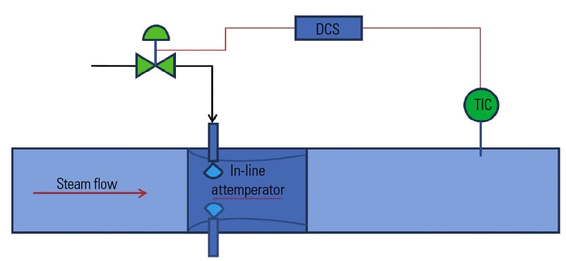
Like standard desuperheaters, bypass desuperheaters extract high-pressure feedwater from the HRSG’s supply line. The water is sent to a valve control station, which sprays it directly into the flow of main steam, reducing its temperature and pressure. The process enables the steam to be recaptured without doing harm to downstream components.
In most combined-cycle designs, however, the in-line piping of the bypass desuperheater lacks the internal lining commonly found in the piping of a standard desuperheater. As a result, spray water makes direct contact with pressure-boundary piping and produces very high thermal and mechanical stresses that can cause multiple through-wall failures within a short time.
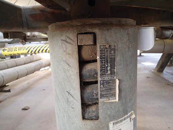
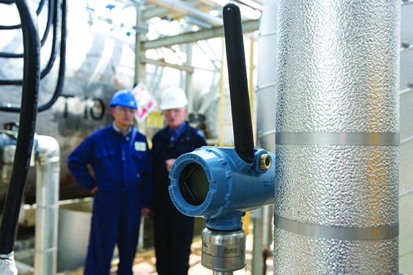
The bypass desuperheater design that has proven most prone to failures has a thick-walled fitting for multiple spray nozzles around its circumference (Figure 1). Failures typically occur on the downstream side of the desuperheater, at the circumferential weld joining thin-walled downstream piping. The cracks that cause the failures usually are found on the inside diameter of the weld (Figure 2).
2. Crack addict. Heavy-walled desuperheaters are particularly prone to cracking on their downstream side, at circumferential weld joints. Courtesy: Thielsch Engineering
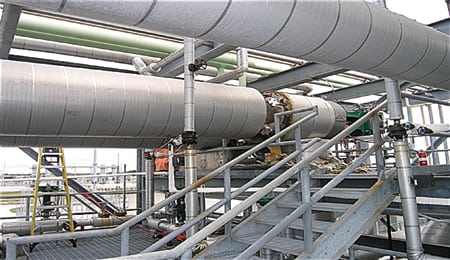
Another common type of failure occurs when thermal gradients created by desuperheater operation apply bending stress to the piping system. In these cases, the telltale cracks appear on the outside diameter of the weld (Figure 3). The results of Thielsch’s finite-element analyses of the magnitude of the stresses on the desuperheater joint indicate that cracking may be initiated after fewer than 100 operating cycles.
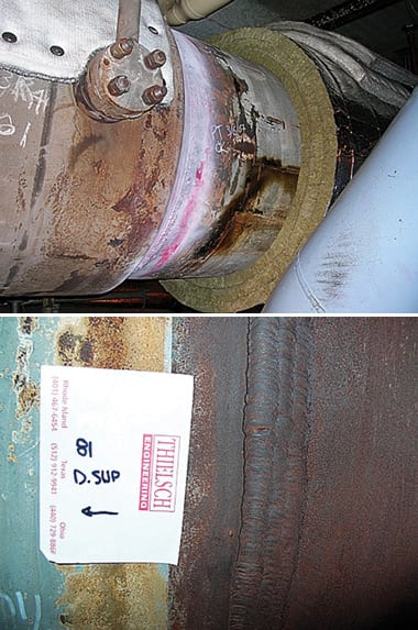
3. Bend over backward. The thermal gradients produced when spray water makes direct contact with pressure-boundary piping create bending stresses. Courtesy: Thielsch Engineering
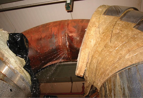
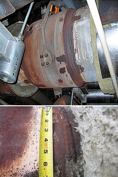
A third type of observed damage has been rupturing of the internal diffuser of bypass desuperheaters (Figure 4). Again, the cause was diagnosed as thermal shock, produced by the contact of cool spray water with hot internal components.
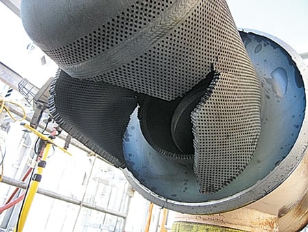
4. Hidden damage. Thermal shock destroyed this bypass desuperheater’s internal diffuser. The unit’s fitting was removed to show the extent of the destruction. Courtesy: Thielsch Engineering
—Contributed by Peter R. Kennefick (pkennefick@thielsch.com) of Thielsch Engineering Inc.
PUMP REPAIR
DSSP, CAD, and fast casting salvage nearly totaled pump
A centrifugal pump might seem an odd thing to be grateful for on Thanksgiving—unless you’re John Allen, maintenance superintendent for Owensboro Municipal Utilities (OMU).
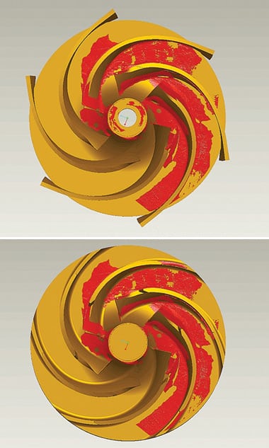
A few weeks before Thanksgiving 2006, a centrifugal pump serving one of the steam turbines of OMU’s 425-MW coal-fired Elmer Smith Power Plant in Kentucky suffered catastrophic damage. Half of the pump’s shroud was destroyed, and the tops of its impeller blades were sheared off (Figure 5).
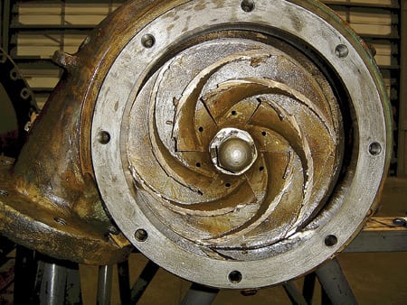
5. Unfit for service. The damaged impeller of the centrifugal pump at the Owensboro power plant, before it was removed. Courtesy: RER
Without the pump, the turbine couldn’t operate, which reduced the plant’s capacity by one-third. There was no backup for the pump because plant management had expected it to last for 40 or 50 years. Nor were there computer-aided design (CAD) models or documentation to help rebuild it.
Under pressure to maintain service to OMU’s 26,000 electricity customers, Allen hired a Wisconsin-based contractor—Rotating Equipment Repair (RER, www.rerpump.com)—to revive the severely damaged pump as quickly as possible, using any means necessary. For the effort, RER enlisted the help of two local partners with unique credentials: Advanced Design Concepts (ADC, www.adcinc1.com), a specialist in digital shape sampling and processing (DSSP), and Signicast Corp. (www.signicast.com), the operator of an investment foundry.
Replicating the design digitally
The rebuilding project began on the evening of November 8, 2006, with RER’s receipt of the damaged pump from the OMU plant. The next day, RER technicians disassembled the pump and began preparing it for reconstruction.
Based on the original dimensions of the pump, the remains of the impeller, and its experience in pump design, RER engineers built a 2-D model of the impeller in AutoCAD (from Autodesk Inc.) and obtained cross-dimensions from it. Over the following weekend, a pattern maker at RER built up an impeller vane in clay to match the specifications of the original.
ADC received the impeller and the AutoCAD dimensional drawings on Monday morning, November 13. The company was a natural fit for this project for two reasons: It is less than seven miles from RER, and it has used DSSP to recreate everything from classic Harley-Davidson gas tanks to cylinder head ports for Nextel Cup race cars.
DSSP enables physical designs to be scanned and automatically recreated as digital models. The process helps companies speed the development of products based on legacy designs, perform accurate engineering analysis using digital models that replicate manufactured parts, inspect finished products faster and more precisely, and continuously improve products over their lifespan.
Accelerating the recreation
Because all of the centrifugal pump’s impeller vanes are identical, ADC only needed to capture one and replicate it for the CAD model. By noon on November 13, Justin Ebbe of ADC had captured the impeller geometry using a Cimcore scanning head with a Romer arm (Figure 6).
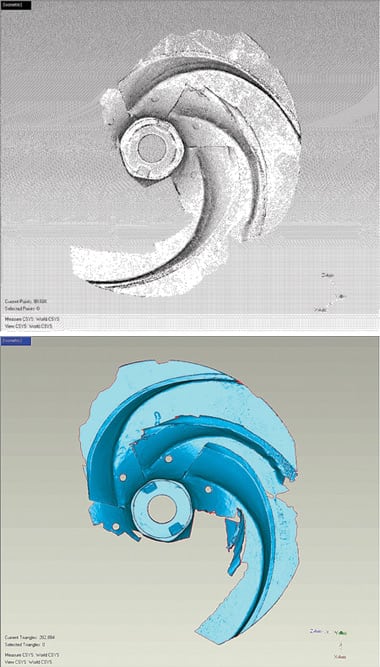
6. Mapping the remains. The first step of the pump rebuilding project was collecting raw point-cloud data from a scan of the damaged impeller (top). Geomagic Studio automatically wraps the point data with a polygonal model (bottom) compatible with Pro/ENGINEER design software. Courtesy: ADC
Ebbe then used the Wrap module of Geomagic Studio software (www.geomagic .com) to quickly align the scan data and "wrap" a polygonal surface model around the point cloud the data produced. Although the wrapping is automatic, users can fine-tune the model as desired. Wrap creates "watertight" polygonal models without approximations. The polygon model was saved as an STL file suitable for use as a guide for the overall CAD model of the pump.
“The STL file representing the polygon model accurately depicted the [vane] in a decimated form that Pro/ENGINEER [from Parametric Technology Corp. (www.ptc.com)] could handle," explained Chris Mulhall, the ADC design engineer who managed the project. "[The compatibility] allowed us to create a model of the part and simultaneously compare it to the scan data."
The Geomagic Studio model served as the starting point for building a parametric model of the impeller in Pro/ENGINEER. To ensure accuracy, Mulhall overlaid the scan data onto the Pro/ENGINEER model of the master vane as it was being created. Exact copies of the master vane were then made and patterned around the impeller’s axis. The geometry of the shroud on the bottom of the impeller was used as the basis of a model of the top shroud (Figure 7).
7. Designing the model. ADC used Pro/ENGINEER to pattern the master vane, making exact copies around the impeller’s axis (top). A model showing the final blade arrangement (bottom) was patterned from a Geomagic scan of the master blade. Courtesy: ADC
The initial plan was to produce a two-part model that would then be machined, assembled, and welded. But some outside-the-box thinking by RER engineers led to a much faster solution.
Casting, the quick way
RER had originally planned to make a sand-casted mold of the impeller. The process would have required building intricate wooden molding boxes by hand and filling them with casting sand or a mixture of sand and clay. That would have been labor-intensive, and the resulting metal castings would have been rough, with a sand-like texture. Sand-casted molds usually require a fair amount of handiwork—hammering, grinding, and sanding—to make them suitable for manufacturing. That takes a lot of time—a luxury RER didn’t have.
“It can take four to six weeks to reserve foundry time for a sand casting, and then another two to three weeks for the mold to be completed,” said Eric Kirschling, the RER mechanical engineer who headed up the impeller project. “So the total turnaround time is eight to 12 weeks, which we couldn’t afford.”
To shorten the turnaround time and increase the accuracy of the mold, Kirschling looked into investment casting. In this process, a wax mold is coated in ceramic and placed in a furnace. The heat hardens the ceramic and melts away the wax, leaving a finished ceramic mold.
RER further accelerated the process by having Signicast create the casting using a rapid prototyping system that produces the mold directly from the CAD model. A hard coating is applied to the rapid prototyped mold, and then the liquid metal is poured into the casting to form the part. "The end product is better quality than a sand casting," said Kirschling. "It’s smoother and has tighter tolerances."
Mulhall had finished the two-part CAD model of the impeller when Kirschling alerted him to the change in plans, which now called for a one-piece model (Figure 8). "It took Chris about an hour to switch gears and create the one-piece representation," according to Kirschling.
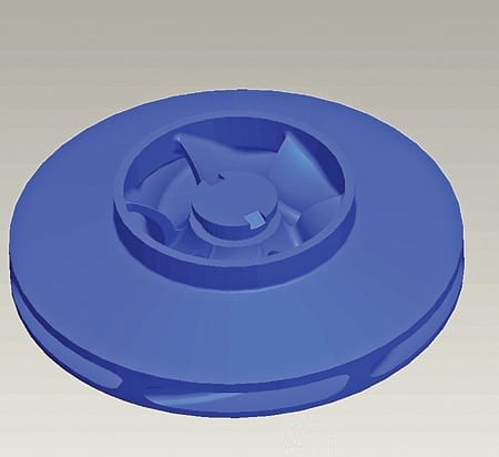
8. Casting call. The CAD model of the impeller prepared by RER for quick casting. Courtesy: RER
The entire digital reconstruction—from scanning to geometry processing to CAD—took just a day and a half. On November 14, RER received the solid model from ADC, ready for quick casting at the Signicast foundry.
A reason to give thanks
Signicast did the rapid prototyping and created three investment castings within a week. RER heat-treated the castings and machined and balanced them by November 22. It assembled the renovated pump (Figure 9) and shipped it by the end of the following day, which happened to be Thanksgiving.
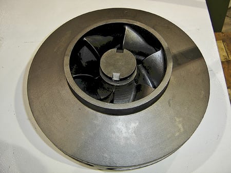
9. Back in the saddle. The new impeller, ready for service. Courtesy: RER
The combined use of DSSP, CAD, and quick casting saved anywhere from six to 10 weeks of time, by Kirschling’s estimate.
In Kentucky, the return to service of one of his generating units gave John Allen another reason to be thankful. While the unit was down, Allen and his team took the opportunity to clean the tank in which the damaged pump had been submerged and to repair the damage caused to piping by the parts of the pump that had shattered.
“Because a spare pump wasn’t on-site or available, it was critical to fix the damaged pump as quickly as possible,” explained Allen. “RER did a great job of getting it back in service as soon as possible, and now we have some backups on hand if a similar failure occurs.”
—Contributed by Bob Cramblitt (bobc@cramco.com), a freelance technology writer.
PLANT MAINTENANCE
Seals of approval
In H.G. Wells’ War of the Worlds, the alien invasion is not stopped by military force but by microscopic organisms. Similarly, in a power plant, the failure of one thin seal can bring down a massive steam turbine.
“We’ve found that spiral-wound gaskets for manways are only good for about six cycles,” reports Stuart Bussman, inside maintenance supervisor at TransAlta Corp.’s 1,404-MW coal-fired plant in Centralia, Wash. “We’d find ourselves starting up a unit, only to have to shut it back down to replace a gasket.”
Less torque, more (sealing) action
Because spiral-wound gaskets have been used for nearly a century, they have proven value in certain environments. Indeed, they dominate the overall market. But for high-pressure, high-heat applications, spiral-wound gaskets are less than ideal.
As a result, Mike Perkins of A.W. Chesterton Co. (www.chesterton.com)—an industrial fluid sealing company—has specified gaskets from Sealing Corp. (Selco, www.selcoseal.com) for such applications for the past 10 years. "I look for issues that shorten gasket life and cause problems for our customers," he says.
Unlike conventional designs, Selco gaskets have a thin layer of convoluted stainless steel and a 0.015-inch graphite coating on both sides. Under pressure, the graphite compresses to the thickness of the stainless steel, forming a tight seal.
This design has several advantages over conventional spiral-wound gaskets. For one, Selco seals can accommodate a wider range of pressures and temperatures: pressures from 150 pounds to 2,500 pounds, steam temperatures as high as 1,200F, and air temperatures from cryogenic to 932F. According to Perkins, this design-induced versatility translates into "a great reduction in inventory reductions, and never having to worry about grabbing the wrong gasket from the storeroom."
Another advantage of Selco gaskets cited by Perkins is the lower torque pressures they require. Because they need to be "crushed" only one-third as much as spiral-wound seals, a sealing pressure of 5,000 psi is adequate, vs. the usual 10,000 to 12,000 psi. As a consequence, the gasket’s flange bolts only need to be torqued to 50% to 65% of the bolt yield. This gives the gasket more room to expand under heat or pressure, with no need to re-torque it. "It also means you don’t have to overtorque the B7 studs," adds Perkins.
“I tend to use these gaskets in high-vibration and thermal expansion situations,” he says. “I use live loading on any part that will be heating up and cooling down more than once a month or will reach an operating temperature in excess of 300F. I also use it on any part that experiences jarring or vibration as a normal part of operation.”
Small seals, big problem
TransAlta’s two-unit Centralia plant entered commercial service in 1971 firing coal from an adjacent surface mine. The plant later switched to Powder River Basin coal to reduce its SO2 emissions. Each of the two boilers is fed by eight pulverizers and generates 5.3 million lb/hr of steam.
TransAlta’s Bussman reports that after a switch from asbestos-based to spiral-wound graphite seals about a decade ago, both units began to experience periodic failures of manway gaskets on their main steam, collecting, and lower waterwall drums. "The graphite seals lost their resiliency quickly and started leaking," he says. "It became a big problem. The gaskets on drum doors were particularly susceptible to leakage, and if the leaks became excessive, we had to shut down the whole unit and replace its seals, at considerable cost, including lost generation revenues."
Looking to solve the problem once and for all, Bussman called Perkins at A.W. Chesterton, who had Selco design a custom seal for one of the manways at the Centralia plant. After it worked like a charm, Bussman ordered Selco replacements for the other manway gaskets. "We’ve been very satisfied with them," he says. "We’ve been using them for four or five years now and have not yet needed to open up any of our drums to replace a failed manway seal."
Bussman adds that during major scheduled unit overhauls the drums are opened for inspection and replacement of all their seals. It’s a simple process, he says, that entails cleaning the gasket’s surface with a wire brush, peeling the backing off one side of the seal, attaching it to the door, and retightening the gasket flange bolts.
NOISE CONTROL
Making gas turbine plants quieter
In many developing countries, ancient national grids strain to supply rapidly growing and power-hungry populations and industries. The all-too-frequent results of transmission constraints are brownouts and blackouts—some planned, many not. The unreliability of power delivery from central stations has both limited the output of local businesses and made multinational firms less willing to invest in poor countries. This restricts their economic development and prevents their citizens from raising their standard of living.
Building standalone natural gas–fired plants is a proven way to get power to the people in the absence of a transmission infrastructure. The solution is increasingly practical, given continuing growth in natural gas pipeline mileage in the developing world and expanded global traffic in liquefied natural gas.
The downside of urban generation
In many poor countries, the transmission grid is so unreliable and heavily loaded that a new gas turbine plant must be sited close to the load it is intended to serve. Often, that means building the plant near or within a densely populated area.
A project developer may not get the reception it expects if it fails to consider the noise its plant will produce. A new gas turbine plant may make a neighborhood much quieter by enabling the shutdown of hundreds of noisy diesel- or gasoline-fueled generators. But the gas plant is far from silent; its combustion air intakes, ventilation systems, pumps, cooling towers, exhaust systems, and transformers emit a broad spectrum of low- and high-frequency noises that can make conversation difficult up to a mile away.
If the plant is located in a valley, its noise can be heard much farther away on the valley’s sides, as a jet engine–type "swoosh." This "echo effect" is particularly problematic for plants sited in a poor city whose surrounding hills may be home to millions. Where that’s not an issue, there’s still the problem of the low-frequency rumble that gas turbines produce during their 15-minute start-ups, which may occur several times a day.
No more noisy neighbors
Most power plants genuinely want to be good neighbors, and that means managing their noise output. But even those that don’t care are being forced to pay closer attention to this form of pollution. One reason is the increasingly powerful voice of the poor and underprivileged worldwide. Helped by Internet-savvy nongovernmental organizations, locals upset by a new power plant can make their case to the global community and taint a developer’s reputation with bad PR for years.
Another notable trend is the growing influence of World Bank noise guidelines that all power plants funded by the organization must meet. Some developing countries have adopted those guidelines in the absence of their own. Also growing in stature are the Equator Principles, whose signatories have committed to not financing any infrastructure project with potentially negative environmental or social consequences.
There is no "magic bullet" to ensure that noise concerns do not derail development of an otherwise-promising gas turbine project. The only viable approach is a combination of technical, social, and political responses.
Combine high- and low-tech measures
The technical response requires conducting a comprehensive noise assessment of the power plant, preferably during its design. Experienced industrial acoustic engineers can determine the levels of noise that a planned plant will emit, and whether they will fall within applicable guidelines. Among their tools are computer-aided noise prediction and abatement models, field-measured noise data, equipment manufacturers’ noise ratings, and project design specifics. If noise levels are predicted to be greater than permitted, the engineers should be able to recommend practical, cost-effective ways to reduce them.
Noise can be reduced at its source, along its propagation path, and where it is heard (the "receptors"). Obviously, the best way to mitigate sound at its source(s) is to choose equipment with a low noise rating. But there are many ways to enclose, shield, and/or baffle even the noisiest of systems—if the project’s budget allows for that. Building an acoustic barrier or earthen berm, or placing gravel pads along the main sound propagation path(s) also can reduce a plant’s noise impact.
Low-frequency noise is often the most expensive to mitigate by isolator pads of crushed gravel, engineered wall or enclosure systems, and/or silencers. Be aware that acoustic barriers are not very effective solutions to low-frequency noise.
If all else fails during the design phase, it may be necessary to relocate the plant to an already-noisy area such as an industrial park or port. However, in the developing world residential development is often ad hoc—unplanned, unexpected, and unpredictable. Assessing the noise impact of the project during its planning phase provides a modicum of defense against this uncertainty by highlighting any potential noise issues down the road—literally.
Golden Rule applies
Building good community relations ahead of time can help reduce opposition to a gas turbine power project. Prepare credible projections of the level and timing of expected noise. Meet with community leaders and build alliances, emphasizing the advantages of reliable electricity service. Also recognize that the judicial systems in developing countries are less predictable than those of industrialized nations, and that projects can be delayed when local customs are not respected.
—Contributed by Dave Bare (dbare@golder.com), a principal of the ground engineering and environmental services firm Golder Associates Ltd., and Jonathan Chui (jchui@golder.com), a noise engineer at the company.