Finding and fixing leakage within combined HP-IP steam turbines: Part II
For Westinghouse (Figure 1) and Allis-Chalmers combined high-pressure/intermediate-pressure (HP-IP) turbines, there are more design (and potential nondesign) leakages to the IP turbine than in General Electric machines. That’s because the former units require balancing the thrust loading of the reaction blading. Leakage can enter the IP turbine inlet, IP turbine exhaust, low-pressure (LP) crossover pipes, and occur between split IP1/IP2 turbines. Its result can be an apparent increase or decrease of IP turbine efficiency, depending on the source.
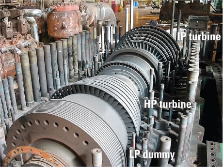
1. In the spotlight. A typical Westinghouse 500-MW BB44 HP-IP steam turbine. Courtesy: Southern Company Generation
Southern Company Generation (SCG) has found that trending of the apparent IP efficiency using the Booth-Kautzmann temperature split tests (discussed last issue in Part I) is very useful for resolving internal leakage problems on our Westinghouse and Allis-Chalmers turbines. It should be noted that the true IP blade path efficiency of these units is difficult to measure.
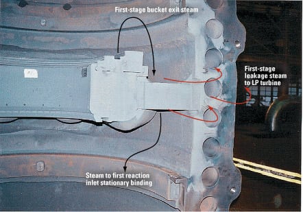
For later (BB44) Westinghouse turbines, the sources of design leakage (Figure 2) include:
- Main steam inlet bell seals (the leakage bypasses the HP-IP turbine; more recent units indicate zero leakage on the design heat balance).
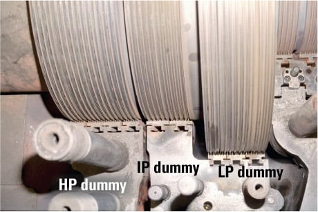
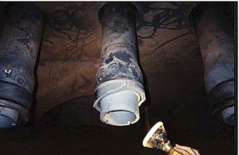
- HP-IP-LP dummy balance seals (Figure 3).
- HP exhaust piston seal rings.
- IP inlet (hot reheat) piston seal rings.
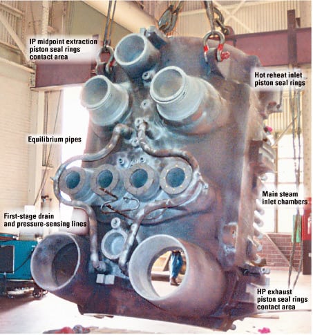
2. Go to the source. Design and nondesign leakage areas on the lower inner shell of a Westinghouse BB44. Courtesy: Southern Company Generation
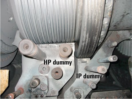
3. To be smart, test these. The HP, IP, and LP dummy seals of a typical Westinghouse BB44. Courtesy: Southern Company Generation
Depending on the unit design, HP dummy seal leakage can affect HP turbine efficiency as it flows through the equilibrium pipes to the HP exhaust. If the IP dummy ring is severely distorted, it is possible for the IP dummy leakage to be a mix of HP dummy leakage and HP exhaust steam flowing in the reverse direction through the equilibrium pipes.
Among the sources of nondesign leakage are:
- The HP inner shell horizontal joint (distorted shell or loose bolting).
- Broken internal equilibrium balancing pipes.
- A broken first-stage drain or pressure-sensing line between the inner and outer shell.
- Piston seal rings on the IP turbine mid-point extraction pipe.
- A missing mid-span balancing port plug in the inner shell.
- Cracks in the main steam inlet pipes at the trepan radius.
Relating efficiency to leakage
For the BB44 design, two values of apparent IP efficiency should be measured. The IP efficiency measured from the hot reheat to the IP exhaust at the blading only takes into account the leakage effect of the IP dummy. The IP efficiency measured from the hot reheat to the LP crossover includes the effects of all HP to IP leakages. The temperature split tests are also used to estimate the IP dummy leakage and the total HP to IP leakage.
Although the test wells provided by the turbine manufacturer at the IP blading exhaust on the upper and lower (difficult-to-access) shells are in stratified locations, they are still useful for trending. Because the deaerator and boiler feedpump usually extract at these points, the temperature of the extraction line also should be measured. On one Southern Company unit that had been retrofitted with a new design IP dummy ring, we also installed two new test wells in the upper outer cylinder just upstream of the hot reheat inlet pipes. The results of testing using these wells still indicated some stratification of IP exhaust temperature.
A broken or cracked bell seal on a BB44 turbine can be diagnosed by trending the difference between the deaerator/boiler feedpump turbine extraction temperature and the LP crossover pipe temperature. If the former is several degrees lower than the latter and the two crossover pipes are at a different temperature, a bell seal or inlet pipe could be cracked.
For units with electrohydraulically controlled governor valves that are individually operated, the manufacturer’s bell seal diagnostic test is useful to perform. Each of the eight governor valves is closed (and re-opened) and the above temperatures are trended. (Exercise caution when doing so on the normal initial opening governor valve, including temporarily disabling the unit trip function.) A change in the temperature differences will be observed on a leaking bell seal when the corresponding governor valve is closed; this reduces but does not eliminate the leakage, which is reverse flow from the first stage, rather than main steam. If the testing indicates that an upper bell seal is the problem, it can be fixed relatively quickly because only the upper half of the outer cylinder must be removed. But if the testing indicates a problem with a lower bell seal, fixing it will not be easy because it will require removing all HP-IP turbine components.
Diagnosing other models
For Westinghouse turbines with an IP1-HP-IP2 arrangement (Figure 4), there are also two values of measurable IP apparent efficiency. The IP1 efficiency is measured from the hot reheat to the IP1 exhaust using vendor-supplied casing pressure and temperature connections in the lower test wells that are somewhat difficult to access on-line. (On some units, there is an extraction location on the IP1 exhaust that can be used for pressure/temperature measurements.)
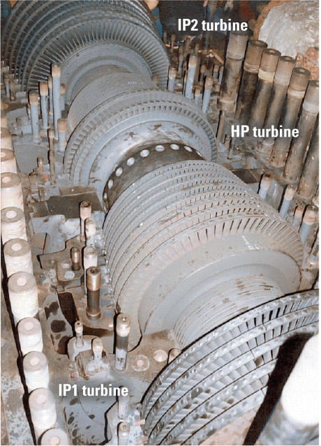
4. Horse of a different color. A Westinghouse 180-MW IP1-HP-IP2 turbine. Courtesy: Southern Company Generation
IP1 efficiency values account for the effect of leakage of HP exhaust steam leakage to the IP1 inlet through the IP dummy seals. The total IP efficiency, measured from the hot reheat to the LP crossover pipe, includes the effects of leakage through the IP and LP dummies, the bell seals, the HP exhaust piston rings, the hot reheat inlet piston rings, the governor valve stems, and the seal at the end of the governor shaft. Possible sources of nondesign leakage include broken equilibrium pipes, a leaking HP-IP1 inner shell horizontal joint, broken first-stage drain and pressure-sensing lines, and cracks in main steam inlet pipes.
Until recently, the only unusual problem that SCG has experienced on the IP1-HP-IP2 type of turbine was a very high IP dummy leakage on one unit, but not on a sister unit. The problem was diagnosed as "extra" cooling holes found in the IP dummy ring, and it was fixed by reducing in size (welding up) the holes, as the existing IP dummy seals would provide sufficient IP inlet bucket cooling steam. A post-outage test revealed that taking this action substantially reduced both IP dummy leakage and total HP to IP leakage. Including the effect of reduced reheat spray flow, the unit heat rate improvement was about 40 Btu/kWh.
Smaller (100-MW and less) Westinghouse turbines have piston seal rings on the main steam inlet pipes. On these units, excessive leakage will reduce HP turbine efficiency as some or all of the HP blading is bypassed. Total HP-to-IP leakage is not affected by this leakage through the piston seal rings.
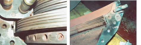
On SCG’s 100-MW Westinghouse turbines, the LP dummy flow (external pipes) to the IP exhaust can be measured using the vendor-supplied flow measurement/restriction orifice plates. On one occasion, the rotor of one unit was visibly thrusting, causing measured LP dummy flow to cycle. The results of temperature split testing were inconclusive due to the swings in leakage. Eventually, the turbine required an inspection to check for wear of its thrust bearing. The root cause of the thrusting was determined to be worn-out IP dummy seals, which were no longer in a hi-lo configuration (Figure 5).
5. Seals don’t lie. A 100-MW Westinghouse turbine with severely worn IP dummy seals that caused noticeable thrusting of its rotor. Courtesy: Southern Company Generation
Later Westinghouse units have a mid-span balance port that can be used for borescope inspections to check for loose HP inner shell bolts and broken equilibrium pipes. On BB44 units, this can also be accomplished by removing an LP crossover pipe.
Allis-Chalmers reheat turbines also are susceptible to several sources of design and nondesign internal leakages. Figure 6 highlights these sources for 75-MW Allis-Chalmers units, of which SCG has three. The sources of design leakage to the IP turbine include the IP dummy, the reheat diaphragm packing, and the LP dummy. Excessive leakage through the IP dummy and reheat diaphragm packing into the IP turbine inlet would produce an increase in measured IP efficiency. By contrast, excessive leakage through the LP dummy into the LP cross-around pipes would cause a decrease in measured IP efficiency. Sources of nondesign leakage include the reheat diaphragm packing housing joint and the horizontal joint.
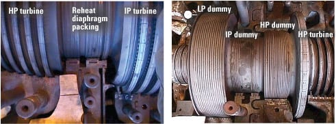
6. Other sources of internal leakage. The HP, IP, LP, and reheat diaphragm packing of an Allis-Chalmers 75-MW turbine (L) and the HP-IP-LP dummy seals location (R). Courtesy: Southern Company Generation
Nondesign leakages—through the two sets of main steam inlet piston seal rings or the HP inner shell horizontal joint, or due to a broken first-stage pressure-sensing line/drain on the inner cylinder—affect the performance/efficiency of the HP turbine, but not leakage into the IP turbine. SCG has used the Booth-Kautzmann temperature split test to trend the leakage rate before and after a turbine outage on Allis-Chalmers units. We also have temporarily opened the reheat diaphragm (similar to the GE N2 packing blowdown test) and balance piston unloading valves to calculate the reheat diaphragm packing leakage and IP dummy leakage, respectively, based on the change in measured IP efficiency.
Recipe for repairs
Reducing excessive internal leakage in Westinghouse and Allis-Chalmers turbines may require taking any or all of the following steps:
- Replacing any HP-IP-LP dummy and reheat diaphragm packing seals with excessive clearance or broken teeth.
- Replacing bell seals or piston seal rings that are cracked or broken (Figure 7) or have excessive clearance/taper or erosion. The inner cylinder nozzle chambers or inlet pipes may require refurbishment if they are eroded or worn. Any unused bell seal retainer nut lock screw holes should be welded up as they can be a source of main steam leakage. Some piston seal ring designs (Figure 8) can produce excessive leakage if installed improperly, upside-down (one side is flat, and the other has alternating high and low sides).
- Checking inlet sleeves for cracks in the trepan radius using the turbine manufacturer’s test method. In Westinghouse BB44s that are routinely found to have cracked bell seals, distorted inlet sleeves could be the problem (a consequence of age); the manufacturer offers a method for straightening the inlet sleeve that SCG has used successfully.
- Changing the usually distorted IP dummy ring on BB44s to an improved design offered by the manufacturer. There’s another good reason to do this: BB44 IP dummy ring bolts broken by the distortion can enter the IP turbine and damage its blading.
- Repairing any broken equilibrium pipes or first-stage drain/pressure sensing lines. Sometimes, a equilibrium pipe can be eroded by a broken bell seal steam jet.
- Closing up or reducing in size any "extra" IP dummy ring cooling holes on IP1-HP-IP2 turbines. (Before doing this, consult with the manufacturer.)
- Inspecting the studs/shell threads of the HP inner shell horizontal joint for possible weld build-up caused by machining of the joint surface. The resulting leakage can actually flow up through the shell holes (Figure 9). The stud nuts should be "sounded" with a hammer to determine if any are loose prior to disassembly. For both studs and through-bolts, it is very important to know what they are made of because the material determines how much they can be tightened.
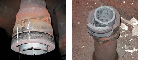
7. Yet another source. Cracked and broken main steam inlet bell seals on a Westinghouse BB44. Courtesy: Southern Company Generation
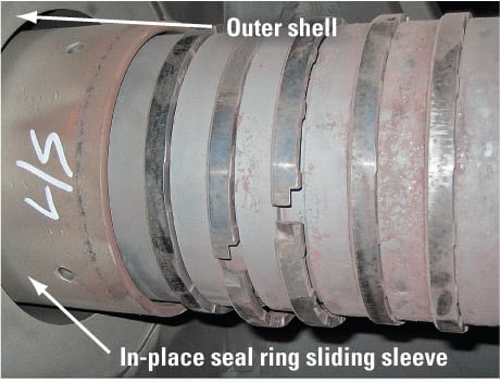
8. One-way street. The alternating (high- and low-side) piston seal rings of a 50-MW Westinghouse reheat turbine. Note that the rings are installed correctly, with the hi-lo side opposite the outer shell. Courtesy: Southern Company Generation
9. Loosey-goosey. Loose HP inner cylinder bolting on both sides of this BB44 turbine caused excessive HP to IP leakage, severely penalizing the unit’s heat rate. Courtesy: Southern Company Generation
After a repair outage, the turbine must be retested to ensure that the work was successful. In SCG’s experience with Westinghouse turbines, less than 6% of hot reheat flow leakage (the design level is 4%) can be achieved with good overall work. Although SCG’s experience with Allis-Chalmers turbines is limited to three units, results indicate that less than 6% of hot reheat flow leakage (design is 3%) can be achieved.
Case study #1: Excessive HP to IP leakage in a 500-MW Westinghouse combined HP-IP drum turbine
In this extreme case, a bad bell seal was determined to be the cause of excessive leakage that raised the unit’s heat rate. The turbine began producing an unusually loud noise following a temperature excursion. A temperature split test indicated that the measured IP efficiency to the LP crossover had decreased 5%, with a significant increase in the LP crossover pressure. Main steam flow had increased 6% although corrected load had only increased 3.2%. The test also revealed that total HP to IP leakage had increased from 6% of hot reheat flow to 13.5%. The temperature rise from the IP exhaust (deaerator/boiler feedpump turbine extraction) to the LP crossover suggested a possible leak through the bell seal or equilibrium pipe.
SCG engineers then decided to conduct the manufacturer’s bell seal leakage performance test. Analysis of that data indicated that closing the No. 7 and 8 valves, which feed a common nozzle block, produced the biggest change in temperature.
Since the No. 7 and 8 valves on this unit are upper inlet valves (narrowing the scope of the problem), the decision was made to remove the upper half of the outer cylinder. Doing so revealed a broken bell seal on the No. 8 governor valve inlet sleeve (Figure 10). Fortunately, the broken portion of the seal could be extracted from the inner shell, minimizing the duration of the outage.
10. Untrained seal. A broken bell seal on the sleeve of the No. 8 governor valve of a 500-MW Westinghouse BB44 steam turbine. Courtesy: Southern Company Generation
Case study #2: Excessive HP to IP leakage in a 500-MW supercritical Westinghouse combined HP-IP turbine
This case is more typical of excessive leakage that goes undetected. Pre-outage temperature split testing of this unit in 1992 indicated a very high level of IP dummy leakage (7.6% of hot reheat flow) and similarly high total HP to IP leakage of 7.4% of hot reheat flow (design is 5.4%). Since it is impossible for the IP dummy leakage to be higher than the total leakage, the absolute accuracy of the IP dummy leakage was called into question. A steam path audit calculated IP dummy leakage of 3% through a distorted ring. Distorted IP dummy rings are a generic aging problem for the BB44 design.
The distortion of the IP dummy ring was "fixed" during the 1992 outage by installing new seals and boring them out off-center. Outage inspections also revealed that a broken first-stage drain pipe and worn HP dummy seals were contributing to the high leakage. The bell seals were in good condition.
Unfortunately, post-outage testing, in 1993, produced worse numbers for IP dummy leakage (13.4%) and total HP to IP leakage (14%). The unit experienced some thrust balance problems after start-up that may have contributed to the higher leakage. Computer models indicated that the leakage raised the unit’s heat rate by anywhere from 32 Btu/kWh to 109 Btu/kWh, depending on its source (first stage or cold reheat). The unit was retested in late 1993 and then again in late 1996. Both tests indicated that both the IP dummy leakage and total HP to IP leakage had decreased somewhat over time, which could not be explained.
Since the distorted IP dummy ring was a known problem, the plant purchased a "modernized" BB44M IP dummy ring from Westinghouse and installed it during a 1999 outage.
Inspections during the 1999 outage revealed some severely worn IP dummy seals (Figure 11) and some with rows missing. The HP dummy seals were also in poor condition, with numerous teeth broken off by axial movement. The LP dummy seals also were worn, and two leaking bell seals were found as well. However, a pre-outage test had not been conducted. If it had been, the total HP to IP leakage would have been much higher than reported by the last readings, in 1996. The dummy seals and worn bell seals were replaced when the IP dummy ring was upgraded.
11. Age takes its toll. A 500-MW supercritical Westinghouse BB44 turbine with a distorted and damaged IP dummy ring seal. Courtesy: Southern Company Generation
The 1999 post-outage test revealed tremendous improvements in IP dummy leakage (1%) and total HP to IP leakage (5.4%) to values near design. A test repeated one year later indicated that both leakage rates had remained near design. Without a doubt, the new IP dummy ring had worked as advertised. The apparent values of IP efficiency, which had been high due to the IP dummy leakage, returned to more normal values. Unfortunately, during the 2004 outage, the replacement IP dummy ring was found to be distorted. Recent testing indicated that the IP dummy leakage rate (4.4%) and total leakage level (7.0%), though not quite as good as the 1999 results, are overwhelmingly better than those found by the 1993 tests.
Case study #3: Excessive HP to IP leakage in a 180-MW Westinghouse combined IP1-HP-IP2 turbine
This case also is typical of excessive IP dummy leakage that goes undetected. For many years, temperature split testing of this unit indicated very high levels of IP dummy leakage (5% of hot reheat flow) and total HP to IP leakage (8.6% of hot reheat flow). Measured values of IP1 and total IP efficiency were always higher than design, indicating significant leakage into the IP1 turbine inlet. The seal clearances of the IP dummy and the horizontal joint of the IP dummy ring, and the fit of the IP dummy ring into the outer cylinder had always been found acceptable. Finally, the mystery was resolved during a 2005 outage inspection. Three 1.25-inch holes were unexpectedly found in the IP dummy ring: one on top and two in the lower quadrants (Figure 12).
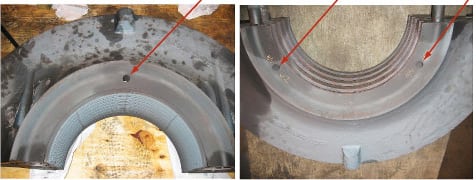
12. Size matters. "Extra" IP dummy ring holes (arrows) for cooling steam on a 180-MW Westinghouse IP1-HP-IP2 turbine. Narrowing them reduced HP to IP leakage rates. Courtesy: Southern Company Generation
A review of the turbine cross section and of detailed IP dummy drawings revealed that the holes were supposed to be there. Flow calculations indicated that these holes for cooling steam were the source of the excess IP dummy leakage (a significant 40,000 lb/hr). After discussions with Westinghouse, SCG decided to reduce the size of the holes to 0.4375 inch by welding and drilling. Post-outage testing confirmed that the work lowered the measured IP turbine efficiency by lowering its HP to IP leakage rates (to 1% for the IP dummy, and to 5.4% for total leakage). On a similar, smaller unit at this plant, the holes in the IP dummy ring were completely welded up in the 2007 outage because a sister unit at another plant did not have the extra cooling holes.
Author’s note: At press time, SCG was investigating a sudden rise in thrust bearing temperature in a 125-MW IP1-HP-IP2 turbine. Further review of the incident indicated sudden increases in measured IP2 efficiencies (one to a heater extraction and one to the LP crossover), along with lower reheat pressures and higher pressures in the IP2 turbine. The problem was determined to be a broken equilibrium pipe between the IP1 exhaust and the IP2 inlet. Unit full load is restricted until an outage can be taken to correct the problem.
—Warren Hopson, PE ([email protected]) is a Southern Company Generation principal engineer for generating plant performance.