Wireless pressure gauges keep nine continuous emissions monitoring systems operating reliably, and wireless position monitoring helps close the loop on 90 control valves.
Existing operations in power plants are often not automatically monitored to the fullest extent possible due to issues associated with adding wired instrumentation. Wireless instruments overcome these barriers by cutting wiring costs 50% or more, reducing installation time 75% or more, and simplifying connections to existing monitoring and control systems.
Florida Power and Light (FPL), a subsidiary of NextEra Energy, operates a 3,800-MW natural gas power plant in Loxahatchee, Florida. The plant had two separate issues where monitoring was desired but not practical with wired instrumentation. The first was related to its continuous emissions monitoring systems (CEMS), and the second was related to control valve positioning.
Power Plant Emissions Monitoring
The Clean Air Act of the 1990s requires power plants and other industrial combustion-related operations to monitor flue gases and comply with the Code of Federal Regulations Title 40 Subchapter C parts 50–97. To comply with these regulations, a power plant has to install a CEMS on each of its emission stacks.
 |
|
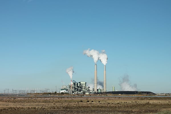
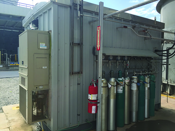
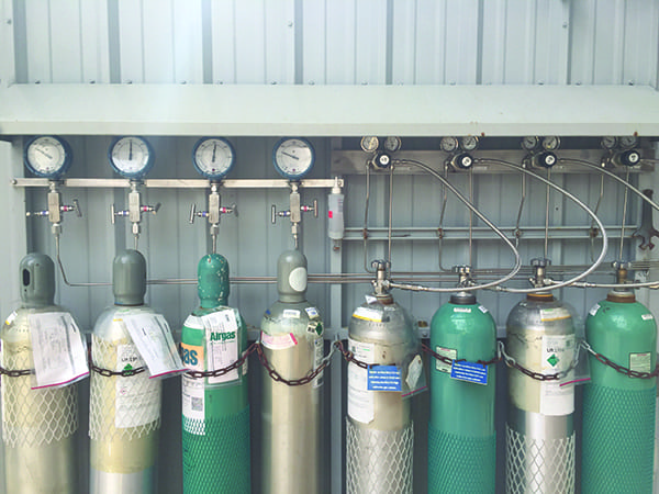
1. Florida Power and Light’s West County Plant in Loxahatchee, Florida, monitors emissions from nine stacks, each having a dedicated continuous emissions monitoring system (CEMS) shack at the bottom. Calibration gases for the CEMS are stored in cylinders located outside the shack. Courtesy: NextEra Energy |
A standard CEMS consists of a sample probe, filter, sample line (umbilical), gas conditioning system, calibration gas system, and a series of gas analyzers. Typical monitored emissions include sulfur dioxide, nitrogen oxides, carbon monoxide, carbon dioxide, hydrogen chloride, airborne particulate matter, mercury, volatile organic compounds, and oxygen. A CEMS shack, located at the bottom of each stack (Figure 1), contains all the necessary analyzers, as well as calibration gas cylinders.
It’s critical that a constant supply of calibration gas is available to the sample analyzers. The calibration gases are required in order to obtain accurate data regarding NOx, CO2, and other gases that are a part of the combustion process. Each CEMS has four cylinders supplying nitric oxide, carbon monoxide, nitrogen dioxide, and nitrogen calibration gases to the analyzers. The calibration gas cylinder pressures commonly range from 2,000 psi to 3,000 psi on average, and each should be replaced when cylinder pressure approaches 300 psi.
At the FPL facility, the calibration gas cylinders were inspected by plant operators during their daily rounds. Duties included recording gas pressures in the daily shift log. If the pressure was lower than 300 psi, the operator replaced the cylinder with a full one located at the shack, and moved another full one from the central location to the specific shack. The manual log process took about three man-hours per day, but inspections could be delayed or postponed if the operator was needed for higher-priority tasks or emergencies. In addition, the rounds were sometimes delayed by rain, lightning, and other issues. Therefore, shift logs were not always up to date. This is critical because if an analyzer calibration fails because there is no gas supply to the analyzers, its data is no longer valid, and the associated unit may be forced into an outage.
As a result, the manual measurement techniques proved less than optimal. Using standard instrumentation techniques, that is, wiring 4–20 milliamp (mA) signals from the pressure gauges back to the control system, would have been difficult due to a lack of existing signal and power cabling to the control system. New wiring would have been needed at considerable expense, and new input points would be required in the control system. A better solution was needed, so the plant decided to use wireless technology.
Wireless CEMS Monitoring
FPL had previously installed a WirelessHART network with three gateways for valve monitoring, so it was a simple matter to install Emerson’s Rosemount wireless pressure gauges (WPGs) on each of the primary calibration gas cylinders and connect them to the existing network. A total of 36 WPGs were installed—four at each of the nine CEMS shacks (Figure 2).
 |
|
2. The cylinder array has spares on the left and in-service cylinders on the right. Wireless pressure gauges are connected to in-service cylinders via high-pressure tubing and block-and-bleed valves. Spare cylinders are capped for safety. Courtesy: NextEra Energy |
Once each WPG was installed at a CEMS, a technician simply entered a key code and followed a simple procedure that identified the WPG to the wireless gateway, which was hardwired to the plant’s Emerson Ovation distributed control system (DCS). It took less than five minutes to activate each WPG.
Emerson’s Rosemount WPG has a 4.5-inch face for local visibility of status and pressure, and it transmits a WirelessHART data signal back to the gateway and the DCS. A gas-pressure-low alarm in the DCS was set to 300 psi as a priority one (red) alarm. When the alarm is seen, the control room operator instructs the outside operator to replace the cylinder, thus preventing calibration failure due to lack of available test gas. For this application, the WPG monitors pressures from 0–3,000 psi. Its data update rate frequency was set to once a minute to improve the battery lifespan to an estimated 10 years.
Plant control room operators now have calibration gas pressures displayed in the Ovation DCS user interface. Operators also have access to the WPGs in Emerson’s AMS asset management software in case they need to review any alert status or other process variable at the specific gauge location.
Temporary lapses in monitoring are allowed by the Environmental Protection Agency; however, any prolonged gaps in recordkeeping can result in substantial fines. This risk has been mitigated with the WPG monitoring capability.
Real-time monitoring allows needed information to be collected, even during times of severe weather and emergencies that made manual rounds difficult in the past. Safety is also improved by reducing the time technicians are required to spend in the field. Eliminating manual rounds is estimated to have saved FPL about $44,000 in labor costs per year.
Wireless Valve Monitoring
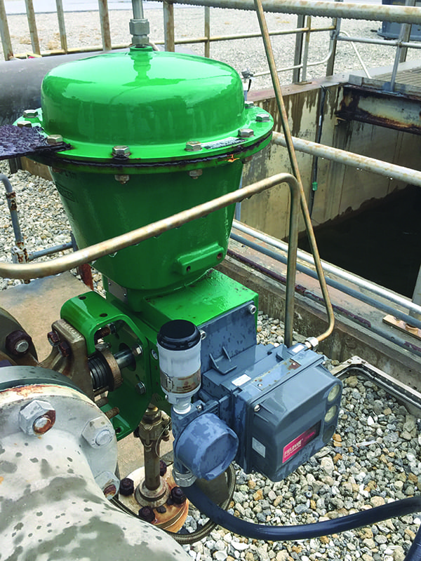
As mentioned, FPL had already installed a WirelessHART network to connect Emerson Wireless THUM adapters on 90 of its Fisher control valves (Figure 3). The control valves and digital valve controllers (DVCs) are located on each unit to regulate natural gas and steam flows associated with the turbines. Adding wireless capabilities allowed each valve to be remotely controlled by operators, a significant improvement as compared to setting valve position locally and manually.
 |
|
3. This image shows one of the 90 Fisher control valves outfitted with a digital valve controller and a WirelessHART THUM adapter. Courtesy: NextEra Energy |
The wireless system consisted of 90 THUM adapters, one per valve, and three wireless gateways to exchange data between the valves and the DCS. Control signals to the valves were part of the original design, but feedback from the valves to indicate position was not. Prior to wireless monitoring, the valves were commanded to a certain position by the DCS and the DVC, but the control room operators had no way of knowing if the commanded position was actually attained. A workaround was to have a field technician stationed at a valve to observe its operation while in radio contact with a control room operator, but this was not a suitable solution.
With wireless, each THUM device converts a 4–20 mA signal proportional to valve position to a wireless signal. As with the WPG signals, these valve-position signals are now visible on the DCS screens in the control room. Plant operators in the control room now have valve position feedback, allowing them to verify the operation of the DVC installed on each valve. This provides accurate control valve position and tighter control to setpoint, increasing efficiency and improving operations.
Successful Improvements
A CEMS is critical to the operation of power plants, and ensuring a constant supply of calibration gases is necessary for the proper operation of the CEMS analyzers. However, monitoring calibration gas pressures manually was not a reliable solution. Installing wireless pressure gauges to transmit data to the control room ensures plant operators are informed when a gas cylinder is becoming depleted and needs replacement.
Like many process plants, this power plant has numerous control valves installed throughout the facility. Without valve-position feedback, or flow feedback downstream of each valve, these control valves were running open loop, with no way of verifying the commanded valve position and corresponding flow was attained. Wireless feedback of valve position allowed control room operators to close this loop and provide precise control. ■
—Robinson Castillo is senior instrument and control engineer for the Power Generation Division of NextEra Energy.