In power distribution systems, three-phase transformer configuration directly impacts system reliability and load management. Understanding the trade-offs between Delta and Wye connections enables engineers to optimize performance.
It is essential to understand the winding configurations of three-phase transformers to optimize performance, manage diverse loads, and control costs in industrial and commercial applications. Each arrangement offers distinct advantages for specific applications. Engineers can optimize system performance, manage diverse load types, and control project costs effectively by understanding the trade-offs between Delta-Delta, Wye-Wye, Delta-Wye, and Wye-Delta connections and selecting the appropriate cooling method.
Engineering Decisions That Define System Performance
In power distribution system design, the transformer winding arrangement fundamentally determines system performance. The configuration (Delta-Delta, Wye-Wye, Delta-Wye, or Wye-Delta) affects the transformer’s ability to manage unbalanced loads, provide neutral connections for single-phase equipment, and adapt to varying voltage requirements.
Beyond configuration choices, three-phase transformers offer significant advantages over three single-phase units. By winding three phases on a single core, manufacturers utilize copper and iron more efficiently, resulting in smaller, lighter, and more cost-effective units for a given volt-ampere (VA) rating. However, these efficiency gains translate into reliable system performance only when the configuration matches the application’s specific requirements. Engineers specifying transformers for manufacturing facilities, data centers, or commercial buildings must understand how winding configurations affect load management, grounding options, and voltage delivery.
Understanding Delta and Wye Winding Arrangements
Two fundamental connection types form the basis of three-phase transformer design: Delta and Wye.
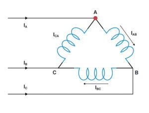
In a Delta connection, the three transformer windings are connected end-to-end to form a closed triangular loop that has no neutral point. Line voltage equals supply voltage, with phase current at approximately 58% (1/√3) of the line current. Delta connections are well-suited for large, unbalanced loads, as the primary provides better current balance to the input power source.
|
1. Delta connection schematic. Courtesy: Bel Fuse |
Without a neutral point, Delta configurations (Figure 1) serve three-phase loads directly and can supply single-phase loads across any phase pair. Center-tapped Delta configurations offer multiple voltage levels and a neutral.
|
2. Wye connection schematic. Courtesy: Bel Fuse |
In a Wye (star) connection (Figure 2), one end of each winding is connected to a central neutral point, while the other end of each winding is connected to one of the three phases. This four-wire system offers built-in dual voltage capability, providing line-to-line voltage for three-phase equipment and line-to-neutral voltage for single-phase loads. It also features a native neutral point for grounding.
Configuration Options: Matching Arrangement to Application
By combining Delta and Wye connections, engineers can select from four standard configurations.
Delta-Delta (D/d) offers robust performance for applications requiring continuous service. If one coil fails, the remaining two can continue to deliver three-phase power at approximately two-thirds capacity. This configuration is ideal for low-voltage, high-current applications and facilities where power interruption would result in significant costs. However, it requires higher turn counts, increasing cost, and provides no neutral connection, limiting its use to three-phase-only loads.
Of the four configurations, Wye-Wye (Y/Y) is the most economical. It has neutral connections on both sides, enabling a dual voltage supply for both three-phase and single-phase loads. There is no phase shift between the primary and secondary voltages, which simplifies parallel operation. However, it requires careful balancing of single-phase loads and is more susceptible to passing harmonic noise between the source and load.
Wye-Delta (Y/d) is ideal for step-down applications at the endpoints of transmission lines. The Wye primary reduces the voltage across individual coils by a factor of √3, which enables fewer winding turns and reduced insulation requirements. Though the grounded neutral provides safety benefits in high-voltage applications, the 30-degree phase shift and vulnerability to single-coil failure must be considered.
The Delta primary with Wye secondary (D/y) configuration has become the preferred choice for commercial, industrial, and high-density residential power distribution applications. It provides three-phase and single-phase power while presenting a balanced load to the power-generating utility. This configuration also effectively suppresses harmonic noise from reaching the secondary side.
Delta-Wye: The Industrial Power Distribution Standard
In manufacturing facilities, these transformers power large three-phase motor drives as well as single-phase programmable logic controllers (PLCs) and operator interfaces. In data centers, the D/y configuration is particularly valuable because the Delta primary suppresses third harmonic distortion generated by information technology (IT) equipment such as uninterruptible power supplies (UPS) and servers, preventing this interference from reaching the power grid. The Wye secondary’s neutral point provides reliable grounding, ensuring stable voltage and preventing fluctuations that could affect server operation. Commercial buildings use D/y transformers to supply heating, ventilation, and air conditioning (HVAC) equipment, elevators, lighting, and receptacle circuits from a single distribution point. Common configurations include 480 V/277 V (North American industrial), 208 V/120 V (commercial), 600 V/347 V (Canada), and 400 V/230 V systems (international).
When specifying D/y transformers, engineers must consider their vulnerability to single-coil failure. If one of the three coils fails, the entire transformer may become inoperative. Additionally, the 30-degree phase shift between the primary and secondary voltages must be considered when paralleling transformers or in certain rectifier installations, as it can result in increased direct-current (DC) circuit ripple.
Dry-Type vs. Liquid-Filled: Matching Cooling Method to Application
Beyond winding configuration, the choice between dry-type and liquid-filled transformers (Figure 3) depends primarily on power and voltage levels.
|
3. Different types of transformers. Courtesy: Bel Fuse |
Dry-type transformers use air as the cooling medium and are available in two main categories. Open-frame units feature exposed resin-impregnated cores and coils rated up to 1,000 V and 500 kVA, while cast-resin coil designs are rated up to 36 kV and 40 MVA. These units are ideal for applications where fire safety is paramount, such as hospitals, schools, office buildings, and facilities with strict environmental controls. They require minimal maintenance and allow easy inspection of internal connections.
Liquid-filled transformers immerse the core and coils in special mineral oil within vacuum-sealed metal containers, with ratings from 6 kV to 1,500 kV and power capabilities exceeding 1,000 MVA. The liquid cooling is significantly more efficient than air, allowing these transformers to handle higher voltages and loads while maintaining smaller physical footprints. However, they require containment systems, regular oil sampling and testing, and additional safety considerations for fire prevention.
Making the Right Selection
Selecting the optimal configuration requires balancing neutral connections, load requirements, voltage ratios, and environmental constraints. Engineers should also assess total connected loads using demand and diversity factors rather than relying solely on nameplate ratings to prevent costly oversizing and avoid undersizing that compromises performance.
For commercial and industrial applications, D/y configurations remain the industry preference. Signal Transformer, a Bel brand, specializes in engineering dry-type, open-frame, three-phase transformers for demanding applications, combining over 50 years of manufacturing experience with cost-effective, reliable designs.
—Anthony Kourtessis is a design and applications engineer with Signal Transformer, a Bel Group brand.