 Cycling a combined cycle plant places additional stresses on all equipment, but the impacts extend beyond the gas turbine and heat recovery steam generator. Plant owners and managers are beginning to see cycling-related damage on steam turbines too. A recent study by the Electric Power Research Institute assessed the ways plants are finding to deal with it.
Many combined cycle gas turbine (CCGT)–based power plants have seen a significant change in their operating profiles over the past two decades. In many cases, plants that were originally designed for baseload or hours-based operation are instead realizing operating profiles that experience high starts, lower-than-expected capacity factors, and a significant amount of load-following throughout the course of the day.
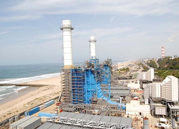
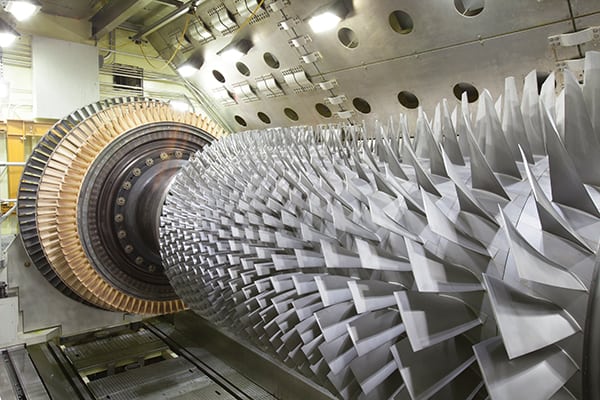
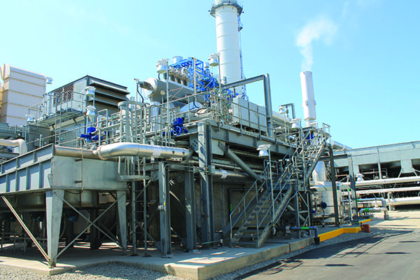
Over the years, original equipment manufacturers (OEMs) and owners have investigated methods to improve the operational flexibility of CCGT facilities, including enhanced turndown capability and increased ramp rates—all in order to improve their market presence. However, much of this work has been focused on the combustion turbine generator (CTG) side of the facility. Very little regard has been given to what shorter start times, lower turndowns, and other modifications to the gas turbine side of the plant may have on the steam side of the facility, with particular emphasis on the steam turbine generator (STG, Figure 1).
 |
| 1. At risk. Though attention has been paid to the stresses that increased cycling can place on gas turbines and heat recovery steam generators, plant operators are now beginning to see similar effects on combined cycle plant steam turbine generators. Courtesy: EPRI |
A recent study by the Electric Power Research Institute (EPRI) investigated the impact of increased cycling on the STG. The study and its findings are described in an EPRI report entitled Operational and Control Strategies for Reducing Steam Turbine Damage from Cycling Combined Cycle Plants (EPRI report 3002006026).
Study Methodology
The EPRI study involved telephone interviews with representatives at a broad range of plants, followed by site visits to selected facilities. Participants were culled from a cross-section of the industry, representing predominantly F-class CCGT facilities, but also including E-class units and aero-derivatives.
In all, telephone interviews were conducted with plant staff at nearly 50 CCGT power facilities in the U.S., Japan, England, and Italy. Interview questions encompassed general inquiries regarding age of the facility, basic design configuration, dispatch operations, plant procedures, and operations and maintenance history of the steam systems in the plant, including the heat recovery steam generator (HRSG), main steam piping, attemperators, and in particular the STG. With regards to the STG, detailed discussions were held regarding maintenance histories, discoveries, inspection frequencies, and lessons learned, all of which also included all STG valves and ancillary equipment. As part of these discussions, the maintenance histories of the generators were also explored. Respondents were asked to share, if possible, integrated plant startup and shutdown procedures.
Interviewees for each facility typically included the plant manager, operations manager, and maintenance manager, or some similar mix of personnel. Interviews generally lasted about 60 minutes. Represented in the study were 127 gas turbines, 81 steam turbines, and eight steam turbine manufacturers (Alstom, GE, Siemens, MHI, Westinghouse, Dresser-Rand, Shin Nippon, and IMO DeLaval).
Steam Turbines in Combined Cycle Plants
As OEMs ramped up their design and manufacturing capabilities for the advanced CTGs delivered in the mid- and late-1990s, they came to the realization that, for the most part, the steam turbine requirements for the new CCGT facilities were drastically different from their fossil-plant cousins. In typical fossil plants, steam turbines will often have as many as seven extractions to provide for feedwater preheating, which is not required in CCGT facilities. In addition, most HRSGs typically incorporate three different pressure levels, in contrast to fossil boilers, which have only one. As a result, most modern CCGT facilities are outfitted with steam turbines that have been specifically designed for combined-cycle operations rather than steam turbines that were originally intended for process duty or fossil-based service.
With the many different facilities responding in the study, researchers received a wide diversity of responses. Some operators stated that they have seen no negative consequences from high cycling of their steam turbines, while others stated that they have seen fairly drastic consequences. One of the project managers interviewed at a non-OEM service provider stated, “There is a lot more being asked of these steam turbines with regards to cyclic duty, and problems are showing up a lot sooner than compared to their older utility-grade counterparts.”
Issues identified in the study were separated into four areas: steam turbines proper, generators, plant startup and shutdown, and control valves.
Steam Turbines
Steam turbines proper have been experiencing a number of problems as the direct result of the cyclic operations.
Airfoil Damage Due to Water or Wet Steam Ingress. Due to the push to get units online quicker, or the desire to try to run at extremely low loads, today’s CCGT facilities have experienced issues with damage to airfoils, both rotating and stationary, resulting in cutting or thinning (Figure 2). This damage is often repairable but can be very expensive and time consuming.
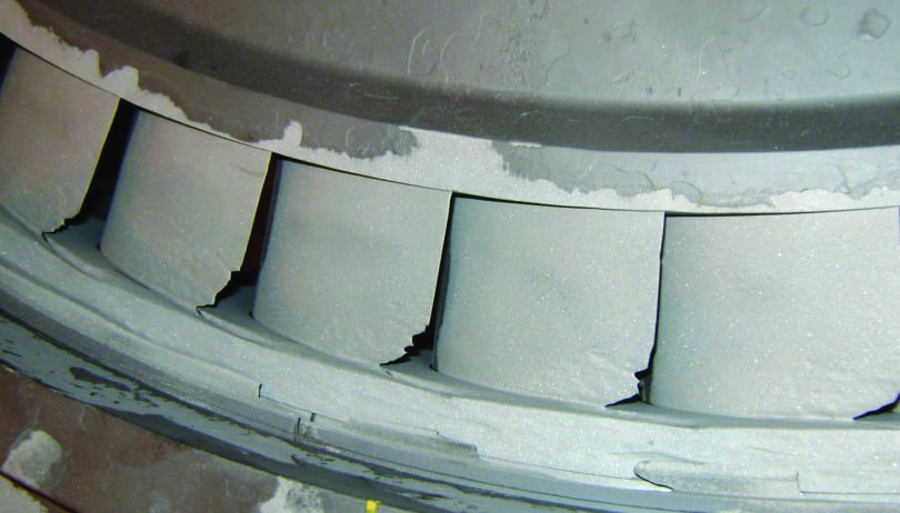 |
| 2. Airfoil erosion. Operation at low to extremely low loads can result in water damage to steam turbine airfoils. Courtesy: EPRI |
Last-Stage Blade Resonance. Surprisingly, a number of issues were noted with a vibrational response in the last-stage blades, resulting from a natural resonance, which has led to the failure of many last-stage blades. This issue has been identified in multiple manufacturers’ units and multiple frame sizes.
Casing Cracks and Deformation. Due to the impact of thermal fatigue and potential water or wet steam ingress, several examples have been documented of casing cracks as well as component deformation.
Rotor Bow. At least one plant, which was the subject of a site visit, experienced a rotor bow to the extent that it required remedial action and will require further repairs during an upcoming maintenance interval.
Managing Differential Expansion. Several sites have noted issues with managing differential expansion, and at least one site had issues with the proper setup and calibration of the differential expansion instrumentation. Having proper knowledge of the proper setup of this instrumentation and proper understanding of how to manage the relative growth between rotor and casing during cycling are critical to preventing potentially significant damage to the critical clearances.
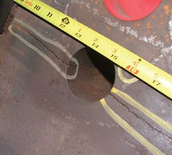
Rubs. Rubs between rotating and stationary components, whether radial or axial, can at best cause momentary vibration and marginal opening of tight clearances, and at worst lead to forced outages to repair the damage (Figure 3). Rubs can be due to a variety of issues, including but not limited to improper maintenance practices, inadequate insulation installation, or poor startup processes.
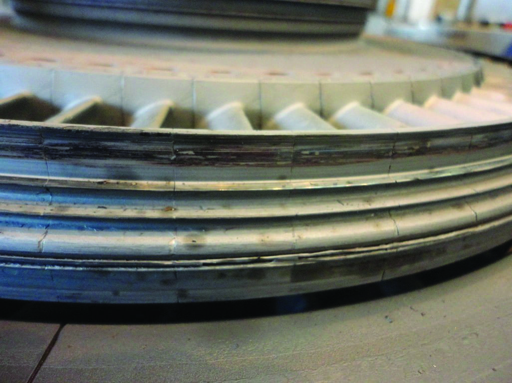 |
| 3. Rubs. Contact between rotating and stationary components can cause vibration and damage. These spill strips have been rubbed and as a result “machined out.” Courtesy: EPRI. |
Generators
Issues with generators on the cycling steam turbines may be the direct result of cycling or exacerbated by the cyclic nature of operations.
Dusting and Greasing. One of the most prevalent issues with cycling generators is loose end windings, which has led to multiple sites experiencing dusting, caused by the rubbing together of adjacent windings. If this happens in the presence of oil that has migrated into the generator, the oil and the dust caused by the friction will create a grease-like substance (Figure 4). The presence of dusting or greasing is not the problem; rather, it is a symptom of a problem that if left uncorrected may eventually lead to shorted turns. Some sites have installed end winding vibration probes to aid in the detection of vibration.
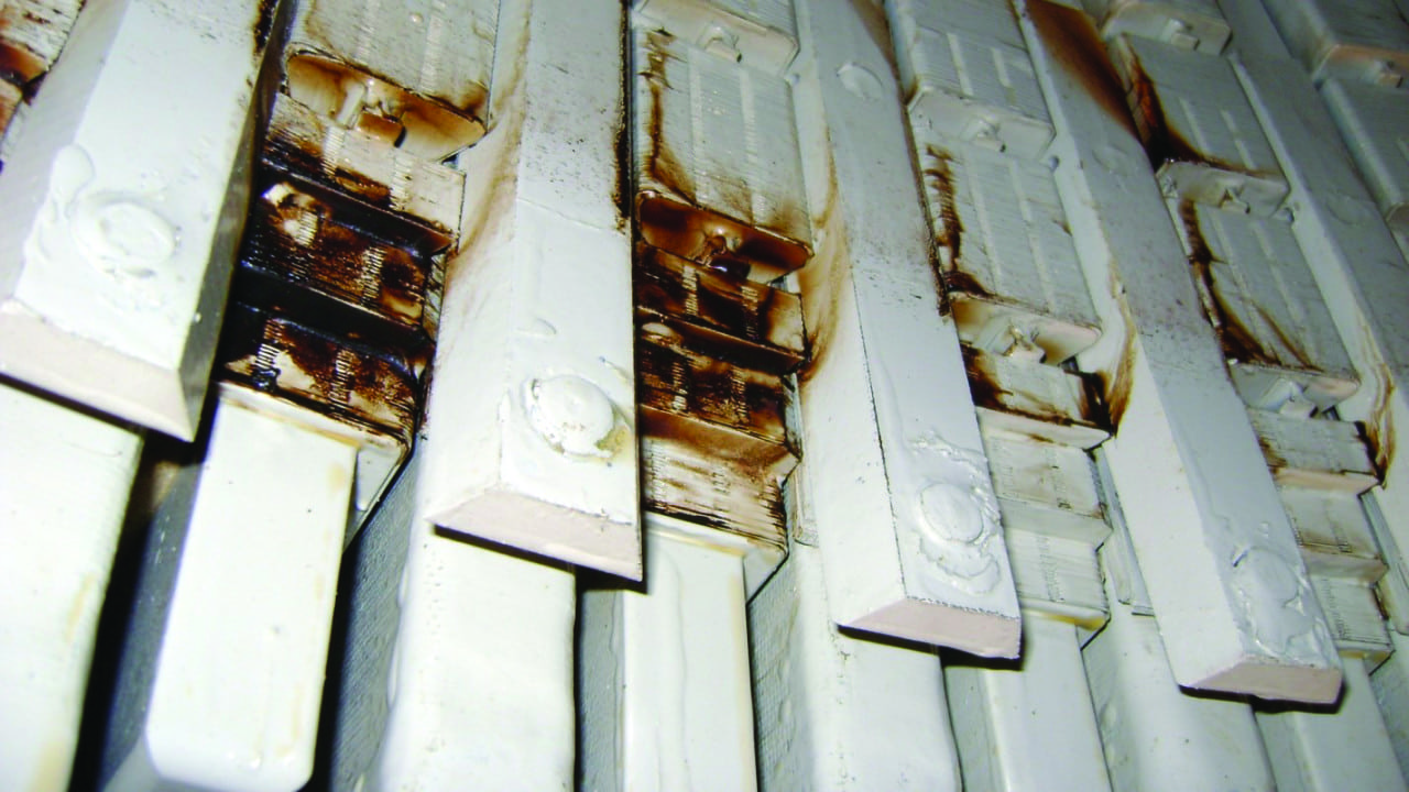 |
| 4. Greasy windings. Cycling can cause additional vibration in the generator, which can manifest as a greasy substance caused by the presence of oil inside the generator combining with dust created by windings rubbing against each other. Courtesy: EPRI |
Oil Ingress. Another common issue with most generators is oil getting in through the oil seals. In hydrogen-cooled generators, this ingress can occur if problems exist with the seal oil pressure regulators. On air-cooled units, it can happen if the inlet air filters become dirty and the differential pressure increases to the point that air is pulled through the bearings. Either way, oil, once it is inside the generator, can atomize with the cooling media, either air or hydrogen, flowing in and around the windings of both the stator and the rotor. This oil can act as a lubricant on windings that are already prone to vibration, as noted above, and can cause them to vibrate much more readily, leading to the greasing described previously.
Thermal Sensitivity. While not specifically a cyclic operational issue, thermal sensitivity in generators has been known to be aggravated by cycling operations.
Rotor Pole Cracking. At least one site reported rotor pole cracking, which was a direct result of the additional stresses placed on this unit as a result of the cycling operations. If such cracking has occurred at this one plant, and it is attributable to cycling, the likelihood that it may occur at other similarly situated facilities is increased.
Control Valves
Due to extreme cycling, a number of issues have been identified with STG control valves.
Thermal Fatigue Leading to Cracking. Naturally, these valves are experiencing multiple heating and cooling cycles, as well as occasional water ingestion or wet steam, which will lead to localized quenching of the components. This quenching, in turn, will lead to cracking of the various components, which may at times be self-relieving. While the cracking may be initiated by fatigue, the cycling will tend to propagate the crack.
Solid Particle Erosion (SPE). Low-load operations, especially in the power blocks of multiple units such as 2×1 or 3×1 that operate in 1×1, keep the control valves pinched back in order to maintain minimum pressure on the HRSG. Because this action will cause the steam to accelerate through the valve, any solids that might be entrained in the system are then jetted through the valve opening, causing SPE on the valve stems. While repairable, this damage is costly and time consuming to fix.
Control Valve Testing/Sticking. A number of factors can cause control valves to stick or fail during a periodic valve test. It can be electrical (for example, the control signal initiating the test or providing test feedback can be interrupted), or it can be hydraulic (such as the solenoid valve experiencing a fault such as varnishing or a clogged filter), or the failure can be mechanical, because the valve itself is actually stuck, and fails to travel when tested. If this happens, proper precautions must be taken to safely shut down the STG without tripping the unit to prevent an overspeed event. Mechanical sticking of the control valve is most likely due to excessive build-up of blue blush within the valve itself. Prudent maintenance practices dictate that these valves be periodically disassembled, cleaned, and the wear parts replaced in order for them to provide adequate STG protection.
Non-OEM Parts. While many sites have had very good luck with non-OEM parts, a few reports were made of incidents involving the use of such parts to repair control valves. While the incidents were not catastrophic in nature, they did require additional forced outages to accommodate the repairs.
Plant Startup and Shutdown
With regards to CCGT plant startup and shutdown processes, a significant variation exists across the industry, and developing a best practices procedure would be beneficial.
Fast Start. An Italian CCGT facility profiled in the EPRI study utilized sparging steam to maintain pressure on all three HRSG drums, as well as steam seals, and established a very impressive record for startup and shutdown efficiency. This site could be utilized as a template for best practices going forward.
Bypass System Shutdown. A facility located in the Midwest has modified its procedures during shutdown to prevent its bypass system from opening in an effort to minimize wear-and-tear on the bypass valves. This site has estimated that the revisions to its startup procedures have realized net savings of $20,000 to $40,000 per year in valve maintenance.
Spreadsheet Startup. Two sites utilized some form of Excel spreadsheet to facilitate startup. Use of the spreadsheet at one site resulted in a site-specific, case-specific, and ambient-specific startup process, while the other appeared to optimize the startup to minimize fuel consumption. Development of a similar type process for best practices might be beneficial.
Siemens X-Crit. A site visit to a plant that utilizes Siemens equipment provided an opportunity to witness the Siemens startup optimization system, which continually checks permissives every step of the way, including what the control room operator referred to as “x-crits,” or rotor-specific variables. Incorporating similar permissive checks, something that considers the OEM stress analyzer, into a spreadsheet type program would be useful.
Site Visits
In the EPRI study, based on the results of the initial interviews, four sites were selected for follow-up on-site visits. These sites were chosen because the plants were doing something unique, were deemed to be industry leading, or had experienced unique problems. Site visits lasted one to two days and, although this was not always possible, were meant to witness a startup and shutdown cycle. During the site visits, additional time was spent evaluating unique practices and how their processes and procedures were implemented and used.
Some unique approaches were observed during site visits.
Thermal Blankets. A plant in the Southwest Power Pool region modified its STG to include heating blankets on the high-pressure (HP)/intermediate-pressure shell to maintain temperatures, helping the plant to all but eliminate cold and warm restarts. These thermal blankets are set to maintain temperatures between 550F and 650F, depending upon the location. The plant is now able to initiate a warm or a cold start, in a 1×1 configuration, and have the plant to minimum stable load (with the gas turbine in Mode 6Q, which means that it meets all environmental regulatory requirements) within 90 minutes.
Spreadsheet. A plant dispatched into the Midcontinent Independent System Operator utilizes a unique spreadsheet to optimize startup sequencing with the goal of minimizing gas consumption during startup. The spreadsheet accepts operator inputs on ambient conditions and calculates unit capacities based on 1×1 and 2×1 operation with and without duct burners and chillers. The operator can then enter projected startup time requirements, and the spreadsheet identifies which steps need to be performed and time stamps each step. This then becomes an ambient-specific, configuration-specific, startup check-sheet.
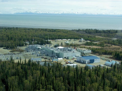
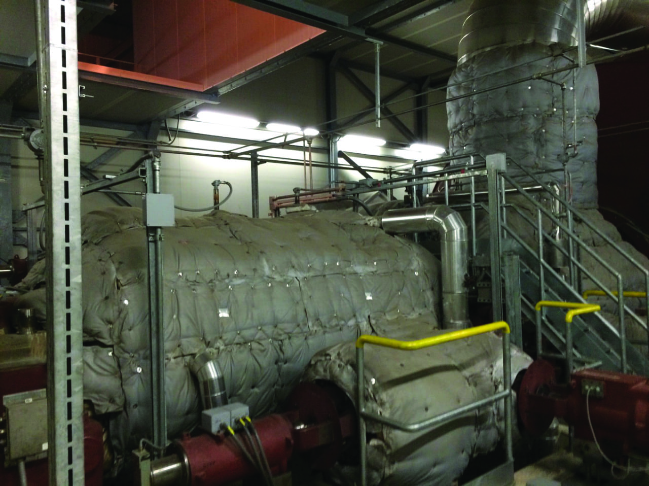
Optimized Startup Sequencing. A unit in Italy has optimized startup sequencing and is able to perform a hot restart on an 850-MW F-class unit in 45 minutes (Figure 5). According to the site, hot starts (STG HP inlet temperature >345C) are about 40 minutes, including a 5-minute purge timer; warm starts (STG HP inlet temperature 220C to 345C) require 1 hour; and cold starts (STG inlet <220C) require approximately 2 hours.
 |
| 5. Start-up sequencing. This combined cycle plant in Italy has developed an optimized startup sequence that enables a hot restart on an 850-MW F-class unit in just 45 minutes. Courtesy: EPRI |
Blades. A 2×1 facility based on F-class technology has had significant issues with the L-0 STG blades caused by water erosion and impingement. This facility also has 3x1x1 7C/E units that have been in operation for about 40 years that have seen severe cyclic duty, and has a 1×1 7EA unit that has also had the L-0 STG blades removed as the result of issues with resonance and tendon failures.
Ongoing Evolutions
A number of issues in the steam turbine and generator suggest further examination to improve cycling response is warranted. The duty cycle of these units will continue to change, and as was seen during the EPRI study, some of the units that are cycling now may in fact move towards a more base-loaded profile, and some that are baseload units now might become peaking units in a few years.
Whatever the case, these steam turbines will continue to see the stresses of cycling operations, and prudent operations and maintenance personnel will have to be in a position to manage this stress. ■
—Merrill Quintrell (mquintrell@epri.com) is a principal technical leader with the operations management and technology program in EPRI’s generation sector.