The right level instrumentation is key to keeping boilers on an even keel. Guided-wave radar offers a critical combination of capabilities.
If asked to make a short list of factors able to improve heat rate for a thermal power plant, accurate measurement of steam drum liquid level would rank near the top due to its influence on boiler performance. This is particularly true as electric power markets and demand patterns change.
Many legacy thermal plants were designed for baseload operation, running for days and weeks at a time with minimal load changes. Now, plants often have to ramp up and down on a daily basis to balance intermittent production from renewables. This takes its toll on equipment, demanding more sophisticated control to maintain efficiency and a desirable heat rate over a wider operating range. Let’s look at level control in boilers and see how this affects efficiency, operation, and maintenance.
Boiler Steam Drum Level
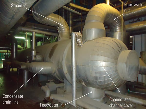
While designs and sizes vary, most subcritical boilers have a drum at the highest point where steam is collected and the tubes come together. Maintaining the right water level in the drum is critical. If the water level is too high, it can be carried into the steam line, and if it makes it all the way to the main turbine, it can damage blades. If the water level is too low, parts of the boiler may go dry and overheat. Both situations can result in long and expensive shutdowns, so a change of only an inch or two in level may cause a trip.
Maintaining this critical level is challenging because a boiler drum is a very turbulent and chaotic place, with high temperature and pressure. Ideally, feedwater should be added at the same rate steam is drawn off. This is manageable when steam consumption is very stable, but when loading goes up and down, level can change quickly. Increasing load draws off steam, causing a pressure decrease in the drum and allowing more steam to bubble in the tubes. This raises the liquid level, and if it is a big enough change in a short time, it can cause a trip. Reducing steam consumption can have the opposite effect.
The American Society of Mechanical Engineers (ASME) Boiler and Pressure Vessel Code PG–60.1.1 requires any boiler operating above 400 psi to have two direct-reading gauge or sight glasses to indicate drum level. This is a bit old-fashioned and harks back to the days of manual control by a fireman at the boiler. The code does allow one of those direct-reading gauges to be replaced by two indirect methods of level measurement, which can include differential pressure (DP), displacers, conductivity, or radar technology.
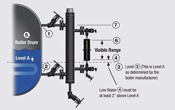
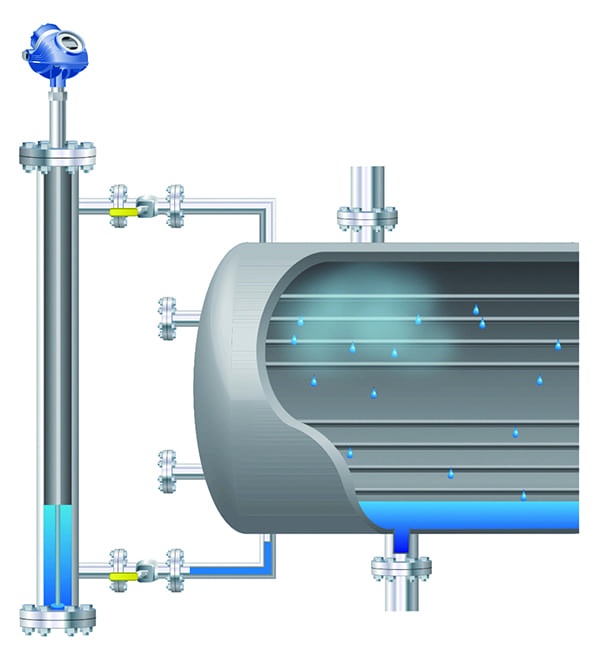
Generally, boiler drum level instruments of all types are mounted using external chambers (Figure 1). This mounting device goes by several terms, including bridle and stilling well, but always includes two connections to the drum—above and below the liquid level—so it will have the same level as the drum itself. Both connections have valves so the chamber can be isolated during operation, allowing an instrument to be replaced or serviced without shutting down the boiler. Chambers also help minimize the turbulence, which is characteristic of boiler drums.
 |
|
1. Boiler drum and feedwater heater level instruments are generally installed using an external chamber (bridle) to simplify maintenance and minimize turbulence. Courtesy: Emerson Automation Solutions |
Level Measurement Approaches
Let’s look at how the four leading measuring technologies work in this context, with pros and cons of each.
DP. DP is a traditional favorite for many applications, but for boiler drums it has some critical drawbacks. First, it depends on knowing the density of the liquid, which can vary enormously in the case of a boiler. The change in water density between 0 psi and 1,000 psi in a boiler can cause an error of 26% for a DP level reading. Obviously, the automation system controlling the boiler will assume a density closer to the operating conditions, but density can still change rapidly based on the amount of bubbling created during an internal pressure change, as discussed earlier. The DP sensor may therefore register a change in level when there isn’t one.
Another serious drawback is the use of impulse lines to reach the transmitter. These tend to be maintenance intensive, requiring regular blowdowns and leak repairs, and they are subject to other sources of plugging.
Displacers. Like DP, displacers also depend on knowing the density of the liquid, so they are subject to the same accuracy limitations. Displacers are mechanical in nature and have moving parts that must operate freely in a difficult environment, often requiring frequent calibration and maintenance.
Conductivity. Conductivity sensors, which are arranged in a line running up the side of the chamber, report level based on how many sensors are immersed. This works and can be highly reliable, but offers low resolution due to the spacing of the sensors. These instruments can be very useful for safety systems, but do not offer the degree of accuracy necessary for level control.
Radar. This leaves radar, which in this context is generally guided-wave radar (GWR), so named for its use of a probe as a wave guide. GWR works well for operating in the narrow confines of a chamber thanks to the wave guide, conferring a number of advantages.
First, GWR does not depend on liquid density. It detects the point at which the dielectric constant (DK) changes at the liquid surface. Second, it is rated to withstand the temperatures and pressures encountered in a boiler environment. Third, it is very precise and capable of updating the reading multiple times per second, so it registers changes very quickly.
The drawbacks of GWR are important, but can be mitigated. First, the transmitter head must be mounted higher than the highest possible liquid level by at least the length of the reference reflector. There needs to be a clear space through which the pulse can pass before reaching the liquid surface. As a result, most existing chambers cannot be used as-is. Some chambers can have an extension added at the top to increase the length, or new chambers may have to be added.
Second, just as DP and displacers are influenced by changes in liquid density, GWR is influenced by the dielectric nature of steam. The radar pulse is slowed when working in a boiler, according to the steam density—higher pressure means slower pulse. Because it takes longer for the pulse to go out and bounce back when passing through steam, if the GWR transmitter is calibrated in air, it will deliver readings suggesting the level is lower than it actually is. The instrument’s transmitter can overcome this problem through dynamic vapor compensation.
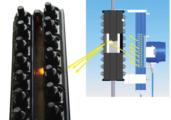
The probe has a diameter step that always remains a fixed distance from the transmitter. Every time it sends a pulse, this step acts as a reference reflector, sending back its own echo along with that of the liquid surface (Figure 2). The transmitter signal processor looks for deviations in the reference reflection time to determine if the signal has been slowed and by how much. It then calculates a correction factor and applies it to the echo from the liquid surface. This operation is performed with every pulse, so the correction is dynamic and reduces measurement error to less than 2%.
 |
|
2. Dynamic vapor compensation calculates a pulse velocity correction based on a known physical distance built into the wave guide. Courtesy: Emerson Automation Solutions |
To avoid problems with water density differences that cause displacements between the chamber and boiler drum, the chamber should be less than six feet from the drum. If beyond that distance, there can be significant density variation between the drum water and water in the chamber, which can cause the chamber to show a different level.
Applying Level Technology
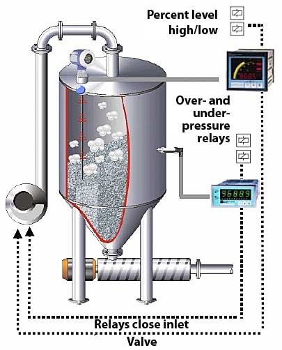
The effects of a boiler upset, either aspirating water into the steam line or allowing part of the boiler to run dry, are serious, so having an appropriate instrumentation and control strategy to prevent these conditions is critical. At the same time, having a false trip triggering a boiler shutdown interrupts production and requires a restart procedure, both of which are very expensive. As a result, operators often use three level instruments arranged in a two-out-of-three voting scheme to initiate a shutdown. This may sound like an elaborate and expensive solution, but losing production just once during a peak output period because of a failed level instrument will more than justify the cost.
Remember that ASME PG.60.1.1 requires at least two indirect instruments, so having a practical voting scheme only calls for one more. The normal installation practice involves mounting three chambers around the drum. If using GWR transmitters, the installers should be careful to ensure the chambers are placed so the top is the required distance above the drum.
Ideally, the three chambers should all be at exactly the same level, and the drum itself should be perfectly level, but often such is not the case. If the heights do not match, the three GWR transmitters will not agree on a level reading. This is because the reading is based on the distance from the flange to the liquid surface, so if the flange positions differ, so will the readings. Laser measuring devices can help quantify the difference so it can be corrected in the GWR transmitters.
If that kind of measurement correction is not practical, installers can use a technique called “floating the chambers.” The three chambers with the GWR transmitters installed are closed off from the boiler drum at the top and bottom. Using a drain port at the bottom of each, they are connected to each other with tubing, with the top of the chamber open to atmosphere. Water is forced in through the tubing so all three chambers achieve the same natural level. This can be a tricky procedure, and it is subject to significant error if not performed properly, so it is usually selected as a last resort.
The readings from the three GWR transmitters can be matched in their configuration to correct for any height differences created during the installation process. If differences emerge during operation, it can be a sign of flow-through or swelling that can cause uneven distribution in the drum. If this proves to be a chronic problem, it might be better to relocate the chambers closer to the middle of the drum.
The necessity for baseload generating plants to modulate their output in response to intermittent output from renewables and other generating sources has made operation more complex. As a result, boiler control has become more critical than ever to keep plants stable. Proper operation depends on effective level instrumentation, and GWR transmitters can fill the bill to maintain stability, efficiency, and profitability. ■
—Matthew Brummer is the North American Rosemount level manager for Emerson Automation Solutions.