Flexible Turbine Operation Is Vital for a Robust Grid
Renewable electricity generation has many environmental advantages, but adding large amounts of far-flung renewable resources to a grid requires increased operating flexibility from dispatchable generators when the wind doesn’t blow or the sun doesn’t shine. One promising option: A combined-cycle plant based on Alstom’s GT24/GT26 combustion turbine can be “parked” at approximately 20% plant load while producing emissions comparable to those during baseload operation—with little loss in thermal efficiency. When demand returns, the combined cycle can return to baseload within minutes.
Renewable generation capacity, mainly solar and wind, has grown rapidly over the past couple of years in the U.S. and several other countries, outpacing all other forms of generation except natural gas. Utilities are developing these alternative generation resources for reasons that range from altruism (it’s good for their customers and the environment) to compliance (a renewable portfolio standard that must be met). Regardless of the reason, adding nondispatchable renewables to an electricity transmission and distribution grid designed for instantaneous demand response adds an additional layer of complexity for power generators and grid operators.
Large generators, such as coal and nuclear plants, were traditionally designed for baseload power supply. As renewable resources have entered service, coal-fired plants in some regions of the U.S. have transitioned into intermediate load plants, and many combined-cycle plants, also originally designed as baseload, are now daily peaking plants. In some locations, combined-cycle plants are “two-cycled” daily: The plant is brought online for the morning peak, shut down or reduced to minimum load, and then started again to meet an evening peak.
To be sure, the fate of gas-fired combined-cycle plants is intimately tied to the price of natural gas. As a result, many are operated only during peak hours of the summer months. The point is that the dispatch order of plants is in flux, as every utility or grid operator uses its unique economic rules and predictive methods to determine how much spinning reserve and dispatchable backup power is required to handle potential grid demand excursions.
The options for providing spinning reserve or backup power for renewable generation are few, and they are all expensive. Sometimes, purchased power can fill the deficit, assuming that sufficient reserve capacity is available. Some electricity suppliers have built small, reciprocating engine or simple-cycle gas turbine plants for the sole purpose of grid stabilization and renewable backup power. Many regions rely on gas-fired simple-cycle or combined-cycle plants as renewable generation backup and live with the practical limits of that decision: The turndown of industrial gas turbines is limited, part-load efficiency is poor, start-up from cold iron is slow, emissions at part-load operation usually exceed permit limits, and adding more start-up hours shortens equipment life.
Usually, the decision about what type of backup power to provide entails making do with current assets rather than installing new ones to optimize evolving spinning reserve and backup power demands on the grid.
An Elegant Solution
If you ask a grid operator or dispatcher responsible for meshing renewable and conventional generation to describe the characteristics of the ideal dispatchable plant, the likely response will be “a gas-fired plant that has quick start-up capability to respond to system emergencies, offers exceptional turndown with rapid load response, stays close to design point efficiency, and meets emissions limits at all loads.” Multiple small gas-fired reciprocating engine plants come close but are not economic when considering a power block of several hundred megawatts. Existing combustion turbines can turn down to about 50% load, but their thermal efficiency drops and emissions skyrocket. Unlikely as it seems, there is a combined-cycle design that has the ideal specifications.
Alstom has developed a Low Load Operation Capability (LLOC) for its KA24 and KA26 combined-cycle power plants, which are based on the advanced GT24/GT26 sequential combustion turbine (CT). The LLOC allows the plant to operate at loads less than 25% while maintaining operation of the steam side of the plant with respectable plant efficiency. The result is a plant design that not only avoids the need for plant shutdown in the evening and start-up in the morning but also remains ready to provide renewable generation spinning reserve. (See the online feature “What Utility Executives Think About the Smart Grid” for evidence that North American resource planners are recognizing the need for this sort of flexible generation.) As an added benefit, this plant’s ability to maintain the highest efficiencies at part-load conditions provides an operator with a competitive advantage in a merchant power market (see sidebar).
There are a number of operational and maintenance implications of Alstom’s LLOC that will be explored in the remainder of this article. The key design features that should be of great interest to both grid operators and plant owners are these:
- The plant can be operated at very low load during periods of low spark spreads (typical overnight operation), and the grid operator can make immediate use of its spinning reserve once spark spreads increase or if emergency power is required by the grid.
- Avoiding unneeded CT start-ups eliminates the CT lifetime penalty incurred for each CT stop/start.
- Plant emissions levels are similar to those at baseload and well within typical permit requirements. Cumulative emissions are reduced compared to parking a power block at a higher minimum load.
- Energy consumption saving during low spark spread periods compared with operating at higher minimum loads.
- Full online spinning reserve, thereby avoiding start failure risks and possible associated grid dispatch penalties.
Unique Combustor Arrangement
In the mid-1990s, Alstom introduced two similar sequential combustion gas turbines: the GT24 for the 60-Hz market and the GT26 for the 50-Hz market. The main technology differentiator for these gas turbines is the sequential combustor design, which is used to increase efficiency and operational flexibility with lower emissions. The GT24/GT26 combustion system uses the EnVironmental (EV) burner in an annular combustor followed by the Sequential EnVironmental (SEV) burner in the second combustion stage (Figure 1). Sequential combustion, also known as the reheat combustion turbine, was commercialized in 1948 by Brown Boveri Co., a predecessor of what is today part of Alstom Power, using two side-mounted silo combustors. Integrating the concept of dry low-NOx EV burner and sequential combustion into a one-shaft engine resulted in the high-power-density GT24/GT26 product line.
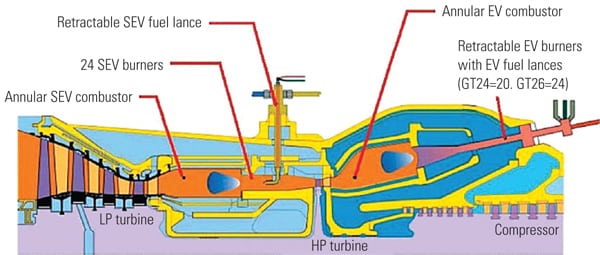 |
| 1. The reheat combustion turbine. The sequential combustion system is a key technology of the GT24/GT26. Compressed air is heated in the first combustion chamber (EnVironmental or EV combustor) by adding about 50% of the total fuel (at baseload). The pressure is halved after the combustion gases expand through the single-stage high-pressure turbine. The remaining fuel is added into the second combustion chamber (Sequential EnVironmental or SEV combustor), where the combustion gas is heated a second time to the maximum turbine inlet temperature. The gas then expands through a four-stage low-pressure turbine. Source: Alstom |
The loading and unloading of the reheat turbine is carried out by varying the setpoints for the high-pressure (HP) turbine inlet and low-pressure (LP) turbine inlet temperature. Also, the three rows of variable inlet guide vanes are operated in a scheme to control the mass flow and allow high part-load efficiencies. Figure 2 shows how the different operational parameters, including the EV and SEV combustor outlet temperatures, are manipulated to achieve the baseload condition.
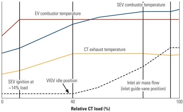 |
| 2. Loading the turbine. The loading of a GT24/GT26 consists of several phases, starting with initial ignition of the EV burners, subsequent ignition of the SEV burners, and loading of the combustion turbine (CT) by opening the variable inlet guide vanes (VIGVs) to allow a greater air mass flow through the CT. When the VIGVs are fully open, the combustor outlet temperature setting of the SEV combustor is further increased to achieve the baseload value. Source: Alstom |
In earlier models, the GT24/GT26 was using a diffusion flame for piloting the EV combustion at low load before switching to premix combustion for the remaining operating range. Since 2005, NOx emissions from the EV burner have been reduced by using an internally staged premix EV burner. Fuel gas is injected in the burner air slots and the center of the burner cone. Both stages are in operation over the entire operation range, from ignition to baseload. The gas is premixed with the air continuously in two stages, with the ratio between the two stages varied, depending on load or gas properties, to reproduce similar gas concentration profiles at the flame location (Figure 3).
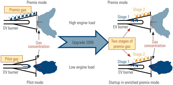 |
| 3. Evolutionary combustor design. Key enabling technologies for the LLOC are not only the sequential combustion technology but also the addition of staged premix combustion in the first combustors for improved emissions control. By properly managing the operation of both combustors, a GT24/GT26 turbine can be turned down to below 20% of rated load yet have air emissions levels similar to those at baseload and well within typical permit requirements. Source: Alstom |
In the SEV burner, where the incoming hot gas has considerably lower oxygen content than normal air, less oxygen is available for NOx formation. Furthermore, because the SEV inlet air is at a temperature considerably higher than conventional combustion air, it requires less heating to reach flame temperature. Both of these NOx mitigation phenomena are known from other combustion technologies that employ exhaust gas reheating. Although a large amount of the total fuel is burned in the SEV combustor, the very low NOx formation in the SEV combustor means that emissions remain low in both combustors.
The LLOC design update takes advantage of the unique dual-combustor design of the GT24/GT26 turbines by actually shutting down the sequential SEV combustor at low part loads while keeping the EV combustor at nominal conditions. This operating capability allows the plant to be operated in combined-cycle mode at a very low combined-cycle loads (less than 25%) with the EV combustor operating in lean premix mode. Lean premix mode ensures low emissions levels as well as a homogenous turbine inlet temperature distribution. This design is significantly different from that of a typical industrial-sized CT that requires combustor piloting or staging at part load. A final advantage: The steam side remains in operation regardless of CT load (Figure 4).
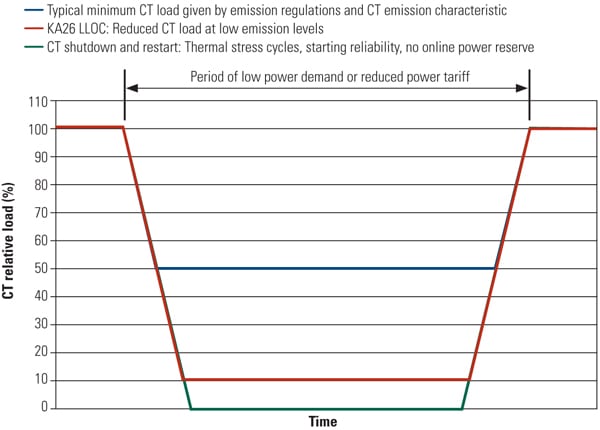 |
| 4. Low-load operation concept. The low-load limit of a typical combined-cycle plant is limited by the gas turbine’s minimum load. The gas turbine’s minimum load may be determined by emissions permit limits or by mechanical design limits such as combustion temperatures, flame stability, or acoustics. The typical minimum load of an industrial CT is around 50%. Source: Alstom |
Favorable Emissions Behavior
The typical measured NOx emissions across a GT26 between the LLOC load range and that of a conventional CT are depicted in Figure 5. Data were collected from the GT26 Test Power Plant in Birr, Switzerland, close to Baden, the headquarters and CT Technology Center of Alstom Power. The data show that the highest NOx emissions across the entire load range remain at baseload, demonstrating that the NOx emission guarantee can easily be met when running the LLOC, unlike similarly sized conventional CTs, which exhibit high NOx emissions at low load.
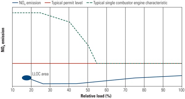 |
| 5. Low NOx at low loads. NOx emissions at part load from a typical industrial combustion turbine (CT) will rise well above baseload permit operating limits. The LLOC-equipped CT, however, can manage the operation of the sequential combustion system to maintain low NOx emissions even at loads down to 20% of baseload. The low-load data were taken from Alstom’s GT26 Test Power Plant. Source: Alstom |
An added advantage is low CO emissions at low load. The EV combustor is operated in a stable premix operation mode so that complete combustion of the fuel occurs independent of load setpoint. This means that CO emissions, essentially partially burned fuel, are also very low and far below typical permit limits across the entire low load range (Figure 6).
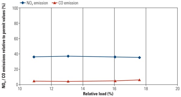 |
| 6. How low can you go? A closer look at GT26 emissions at Alstom’s Test Power Plant at very low loads reveals how flat emissions remain. For reference, the current EU statutory limits are 25 ppm (15% O2) at baseload for NOx and CO emissions below 5 ppm. Source: Alstom |
The sequential combustion system design of the GT24/GT26 CTs produces NOx emissions regularly measured well below current statutory limits (in the EU) of 25 ppm (15% O2) at baseload with no additional water or selective catalytic reduction, and CO emissions below 5 ppm.
Operating Advantages
Integrating the LLOC into a combined-cycle plant design began with the requirement to maintain the bottoming cycle design and operating requirements as close to standard as possible. Particular attention was paid to keep the loading and unloading procedures uncomplicated, and hence reliable, while minimizing the risk of forced shutdowns. The plant control scheme ensures that at any time during a low-load cycle that the plant is ready for reloading with normal plant load gradients from the low-load operation point to a new dispatch load. The LLOC concept was initially tested using Alstom’s cycle simulation models, ensuring feedback on the selected functional and control concepts before applying their findings in a live plant.
From the design and simulation results, the key elements of the LLOC-equipped combined-cycle control sequences were developed (Figure 8). Simplified, the functional operational sequences are categorized into the following operating phases:
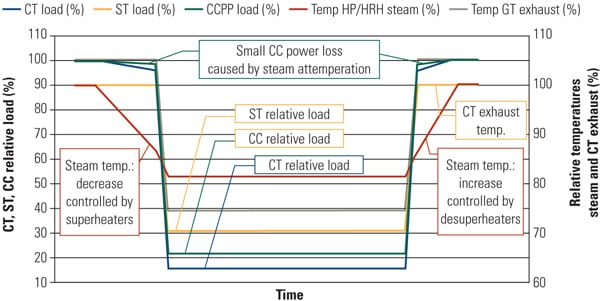 |
| 8. Principles of operation. Alstom’s sequential combustion system gives the GT24/GT26 the ability to maintain a high and constant exhaust temperature for the heat-recovery steam generator (HRSG) down to a part load of 40%, resulting in much higher part-load combined-cycle efficiency compared to that derived from a typical single combustion turbine. This figure illustrates the GT26 low-load hold point. A step-by-step description of the loading and unloading process is included in the text. The dynamic response of HRSG, steam cycle, and steam turbine is simplified. Source: Alstom |
- Phase 0: Initiation and release of plant unloading. The low-load operation mode is selected by the operator, and the rest of the control processes (the next three phases listed below) follow automatically.
- Phase 1: Steam conditioning. In order to keep the thermally induced stress of the steam turbine components within allowable limits, the temperature of the HP and hot reheat (HRH) steam will be decreased to a software-determined target value. Steam turbine power output and efficiency are marginally decreased by the temperature reduction.
- Phase 2: Combustion turbine unloading. When the new steam target temperature is reached, the gas turbine reduces load using its normal unloading ramp rate. The steam desuperheaters close with decreasing CT exhaust temperature. Within approximately 20 minutes of starting the GT unloading, the low-load operation point is reached. For a plant with two CTs serving a single steam turbine, the CTs will be unloaded simultaneously.
- Phase 3: Plant operation at low load. At the low-load operation point only the first EV combustor of the CT is used; the SEV is switched off to maintain low emission levels.
- Phase 4: Initiation and release of plant reloading. Low-load operation mode will be deselected at the operator station. The operator enters a plant load setpoint. CT and steam turbine remain in continuous operation.
- Phase 5: Plant reloading process. In principle, the reloading sequence reverses the unloading process. The CT loads at its normal ramp rate and the water injection valves of the steam desuperheaters open in order to control steam temperature gradients. After approximately 20 minutes, the CT can reach baseload operation, and >95% of the combined-cycle baseload output is available. The steam desuperheaters will gradually close and increase the HP and HRH steam temperatures to nominal values.
Gissi Plant Gets First Commercial Installation of LLOC
The first application of Low Load Operation Concept (LLOC) technology was at Abruzzoenergia SpA’s 800-MW Gissi combined-cycle plant located in the Abruzzo region of central Italy. Alstom was contracted to design, supply, install, and commission the entire power plant. The fast-track project was given the green light in January 2006 and the plant entered commercial service in early 2008 (Figure 7).
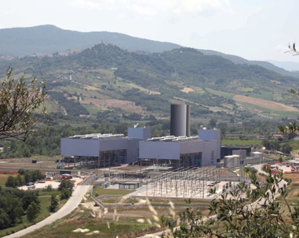 |
| 7. Italian plant design. The first commercial application of Alstom’s Low Load Operation Capability (LLOC) was with the two KA26-1 units installed at Abruzzoenergia’s Gissi plant. “KA26-1” designates a single-shaft driveline combined-cycle plant based on Alstom’s GT26 combustion turbine. Each unit is rated at a nominal 400 MW. The LLOC design feature allows Abruzzoenergia to “park” the plant during low power demand periods at about 20% (~80 MW) combined-cycle load. CO and NOx emissions are kept below baseload permit limits while the plant is parked. Courtesy: Alstom |
The Gissi plant consists of two GT26 sequential combustion turbines installed in a 2 x 410-MW single-shaft combined-cycle arrangement. Each power train comprises one GT26 gas turbine, a triple-pressure reheat, horizontal heat-recovery steam generator, an STF15C steam turbine using 565C/140 bar high-pressure steam, and a shared hydrogen-cooled TOGAS turbogenerator, all manufactured by Alstom.
Initially, Abruzzoenergia planned to shut down the Gissi plant overnight when electricity demand was low. The Gissi plant design assumed two different operating modes: operate about 8,000 hours per year at baseload or about 3,000 hours per year with daily start/stop operation. However, the possibility of low-load operation using LLOC presented Abruzzoenergia with a financial opportunity. The ability to keep the plant online overnight meant Abruzzoenergia could provide power for grid support as well as rapid peak load response. Grid support at night is especially valuable in Italy, which suffered a massive blackout in 2003 caused by a lack of spinning reserve when it was critically required.
However, combined-cycle power plants in this region of Italy usually do not operate at night because emissions regulations historically have prevented combustion turbines from operating at less than 60% of rated load.
Shutting down a combustion turbine and steam bottoming plant overnight, only to restart them the next morning, is a less-than-desirable operating scheme. Daily cycling causes thermal stresses that will shorten the life of major plant components and increase operating costs over the plant’s lifetime as every start-stop operation avoided will save 10 equivalent operating hours. The extended time necessary to start up the plant can also result in lost revenue in a competitive merchant power market.
Alstom’s LLOC allowed Abruzzoenergia to park each unit at less than 100 MW during off-peak hours as an alternative to daily cycling. Each GT26 combustion turbine met the baseload plant emissions requirements while parked.
The units are required to achieve 30 mg/m3 for NOx and CO in all ambient conditions down to 30% load.
In addition, when parking the plant at around 20% combined-cycle load (made possible by shutting down the second or Sequential EnVironmental combustor of the GT26 at low loads, while keeping the first or EnVironmental combustor operating at nominal conditions), emissions are about the same as at full load.
Plant tests have confirmed that the combustion turbine can reach baseload operation and the plant can achieve over 95% of combined-cycle baseload output in less than 20 minutes from the “parked” condition of 20% load.
At a gas price of €0.26/m3 and an off-peak electricity price of €28/MWh (during low-load operation), plant owners expect to save between €10 million and €18 million over the plant’s lifetime. Additional revenue is expected from providing valuable grid frequency support and spinning reserve capacity.
After the simulation phase, the LLOC design was next tested in the GT26 Test Power Plant. During this test and validation phase, data across all possible loads in full combined-cycle mode were recorded in order to verify the plant’s low-load and response capabilities.
Actual results confirmed that the power plant can be loaded from a “parked” condition (about 20% of combined-cycle load) to baseload (100% load) in less than 25 minutes with standard load gradients, whereas normal start-up times for hot start of a combined-cycle plant after an 8-hour shutdown are typically above 40 minutes. In addition, the overall combined-cycle efficiency was approximately 60% of the baseload plant thermal efficiency.
— Dr. Robert Peltier, PE is POWER’s editor-in-chief.