Sleek wind machines both on land and in the ocean intrigue many people. The units provide clean energy and contribute nothing to climate change. However, the early history of wind power in the U.S. included some interesting trials that bear no resemblance to the majority of today’s modern turbines.
Many wind enthusiasts are aware of the big 1.25 MW machine on Grandpa’s Knob in Rutland County, Vermont, which began operation in 1941 (see sidebar “Historical Accounts”), but who remembers the Madaras Wind Rotor in Burlington, New Jersey, built in 1933? It was a vertical axis machine with a very interesting conceptual design for a farm of wind rotors based on railroad technology.
| Historical Accounts
The Vermont machine was the first and only MW-sized wind-powered machine to operate until 1979. Its history is captured in a classic text, Power from the Wind, by Palmer Putnam. The book also contains references to the Burlington wind rotor. Putnam, an engineer, wind power pioneer, and keen observer of national energy needs, also penned Energy in the Future, which was published in 1953. |
A Prototype for the Ages
In the early 1930s, Public Service Electric and Gas Co. was the host site for a large-scale test of a vertical axis wind turbine known as a Madaras wind rotor, operating on the Magnus effect. Six national electric utility companies sponsored the $140,000 demonstration project at Public Service’s Burlington generating station site in western Burlington County, New Jersey.
To envision the concept, imagine a large diameter cylinder rotating about a central axis (Figure 1). This entire rotating structure would be mounted atop a flatbed railroad car. Mechanical power captured from the wind (see sidebar “The Magnus Effect”) would be converted through gearing to drive the wheels of the railroad car. The propelled rotor car would then progress around a large circular track, and through generators coupled to the wheels, produce electric power to be collected through an electrified third rail system. Power generated would be fed directly back into the utility grid via a high-voltage line connection.
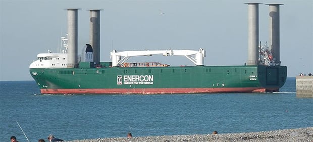 |
1. Standing tall. This image shows wind rotors mounted on E-Ship 1, which are very similar to the design Madaras built in 1933. The four cylinders on the ship are about the same height as Madaras’ but only about half the diameter of his design. Courtesy: Creative Commons/Lpele |
| The Magnus Effect
Baseball pitchers use the Magnus effect when they apply spin to a ball as it moves through the air, causing it to curve. In Madaras’ system, wind moving across the face of the large cylinder would cause the cylinder to rotate. In this case, Mother Nature “pitches” wind at the machine instead of the baseball pitcher throwing a curve by spinning the ball. In one case, the wind moves, in the other, the ball moves. Spin is the commonality. |
An Unusual System
Madaras’ rotor was 90-ft tall, about 22 to 28 feet in diameter, and weighed 4,000 pounds (two tons). The initial conceptual design called for 20 moving rotor cars that could begin generating electricity in winds of 6 mph. The cars would move along a set of circular rails that measured thousands of feet in diameter. Each rotor car would feed a 1-MW electric generator, with the whole system of 20 cars capable of generating 20 MW of power. (A later design envisioned 50 or more rotor cars.)
The 20 rotor car design, with its large circular track, would occupy about 200 acres, or just a little under a third of a square mile. To put this into perspective, a typical golf course occupies 100–150 acres. Each rotor car would be separated from the next by about 250 feet as it moved along the circular track—the whole system being a kind of wind energy carousel.
The gage of this circular railroad track (the space between the rails) was designed to be 30 feet. (The vast majority of North American railroads use a much smaller track gage of 4 ft 8-1⁄2 in.) This wide track gage for the wind rotor car was needed to support the 22-ft to 28-ft diameter of the wind rotor itself.
The diameter of the circular track was expected to be about 3,600 feet (more than 1/2 mile). Each rotor car would measure 40-ft long and weigh 150 tons. The rails would be firmly set in concrete. The circular track was designed to allow the turbines to take advantage of winds coming from any direction.
On October 20, 1933, the trial-unit rotor was first demonstrated. Storm damage ended the rotor testing. Although trial testing of this wind rotor was not successful, it serves as an important chapter in the long march to the practical use of wind energy.
—Harry T. Roman is a retired engineer, research and development project manager, teacher, inventor, and author. He has 12 patents to his credit and is a past recipient of the New Jersey Inventor of the Year Award, given by the New Jersey Inventors Hall of Fame.