Operating pulverized coal-fired boilers under low-load conditions presents several challenges. This article offers tips to keep units in the best possible operating condition.
In today’s energy market with the increased penetration of renewable energy and high-efficiency combined cycle power plants, many of the once-baseloaded pulverized coal (PC) power plants must cycle and/or operate at low load. Many PC plants are operating at 25% to 50% of their maximum continuous rating during periods when renewable energy supply peaks. This is exposing new operating challenges that impact not only the efficiency of the plant at these loads but also the reliability of the boiler.
Grid stability and reliability depends on the coal fleet for rapid load changes as renewables are ramped up or down. In the summer and winter during extreme weather, coal plants are depended on for major electric generation. Storm Technologies’ experience with low-load operation and the challenges it can present date back to before the recent operating characteristics of today’s plants. Most professionals in the power industry are aware of the additional stresses cycling or low-load operation can have on the boiler materials, dissimilar metal welds, and water chemistry to name a few. Conversely, Storm has found that there are a number of improvements in operations and maintenance controllable parameters that are of comparable low cost and often overlooked. These changes when addressed and monitored can improve the operational flexibility and the reliability of the overall plant.
Pulverizer Operation
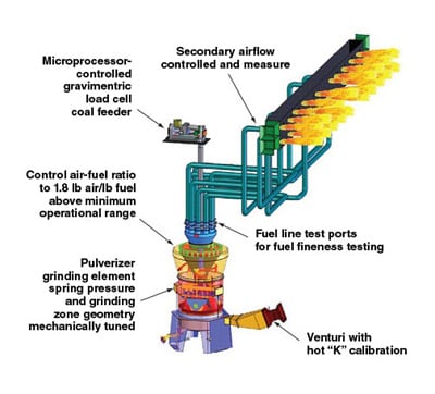
While cycling or operating at low load, the pulverizers at some point are operating on the lower end of the primary air ramp or what is referred to as the minimum air setpoint (Figure 1). At this point, the pulverizer is most susceptible to coal rejects. Coal rejects are considered a “stealth” heat rate penalty by Storm Technologies; it is also a safety concern due to the raw fuel that is spilling through the throat and is exposed to the hot primary airflow in a very air-rich environment.
 |
|
1. Primary air ramp versus pulverizer loading. Courtesy: Storm Technologies |
If coal rejects appear when operating at lower throughputs, it is often directly related to the lower primary airflow, resulting in a lower free jet velocity through the pulverizer throat. Addressing how many pulverizers are needed for operating across the entire load range of your boiler should be an easy enough task and something operations likely has a procedure for. However, Storm often finds plants could be operating with less pulverizers in service, but operators simply choose not to cycle pulverizers out of service. This reduces the throughput through the pulverizers and in many cases results in pulverizers operating on the minimum air portion of the primary air curve.
Figure 1 illustrates a simplified example that by removing two pulverizers from service and operating with only two pulverizers, you effectively increase the primary airflow through the operating pulverizers by moving to the sloped portion of the primary air ramp. As a result of removing the pulverizers from service, you increase the velocity through the throat of the pulverizers in service, which in most cases eliminates the coal rejects that can plague pulverizers at the minimum air setpoint.
Barring a mechanical problem within the pulverizer, coal rejects are almost exclusively related to the geometry of the pulverizer throat for a given set of inlet conditions. If the open area around the throat is sized such that the primary air velocity drops below 7,000 feet per minute (fpm), then raw coal will begin spilling out of the pulverizer. Again, this in most cases results in wasted fuel and increases the potential for an excursion.
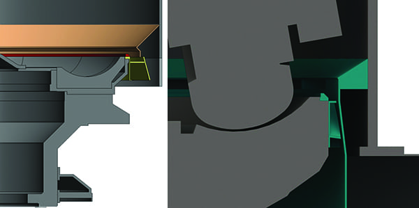
For many years, Storm has been applying engineered solutions to increase the throat velocities so that at the minimum air setpoint the pulverizer throat velocity is 7,000 fpm and there are no coal rejects by installing a Storm-designed rotating throat and deflector assembly (Figure 2). Through the years, there has been one concern that plant engineers have had with this proven design, that is, by reducing the open area immediately surrounding the throat, the pressure drop across the throat increases as the primary airflow increases. As a result, Storm engineers designed and patented an adjustable throat that relieves the increased pressure drop at higher primary airflow rates, while maintaining the required 7,000-fpm throat velocities at the minimum primary airflow setpoint. This is effectively done by providing a second primary air path to the pulverizer and accurately controlling the primary airflow to each zone by a calibrated venturi. Overall, both the original and new patented Storm throat designs will eliminate coal rejects associated with operating a pulverizer at low throughputs, which can improve the reliability of your power plant.
 |
|
2. The original Storm rotating throat and deflector is shown on the left, with the newer Storm-patented adjustable throat design shown on the right. Courtesy: Storm Technologies |
Out-of-Service Burner Health
When a PC plant designed for baseload operation has to follow the grid demand and operate with pulverizers out of service, it can be extremely detrimental to the health of the pulverized coal burners that are out of service. Many readers may think that when the pulverized coal burner is in service, that is when the burner materials will be subjected to the greatest amount of heat, due to the 3,000F flame that is being held from six inches to 12 inches off the tip of the burner. However, the exact opposite is true.
While the burner is in service, the burner nozzle on most U.S. units has an air-fuel mixture passing through the nozzle that is typically anywhere from 135F to 180F, which effectively cools the burner to a metal temperature of 300F to 400F while in service. Once a pulverizer or set of pulverized coal burners are taken out of service, that’s when the metal temperatures begin to increase significantly.
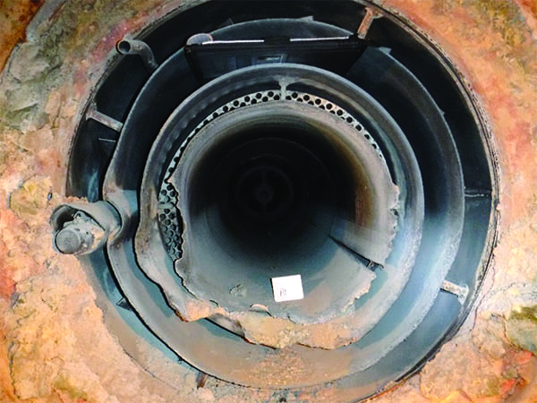
Today’s burners, when out of service, are no longer designed with any cooling air supply, as they once were. Therefore, this leaves all the cooling to the secondary air, which on average is about 650F. When a burner is out of service, it is then exposed to extreme amounts of radiant heat from the combustion process in the burner belt zone of the furnace. This can quickly increase burner metal temperatures above 1,400F. When burner nozzles are exposed to these temperatures over time, they begin to warp and crack as shown in Figure 3, which is detrimental to burner efficiency.
 |
|
3. Burner damage due to overheating. Courtesy: Storm Technologies |
Storm has always been a proponent for installing pad-welded thermocouples approximately six inches back from the tip of the nozzle as shown in Figure 4. These thermocouples can then be monitored in the control room to ensure an adequate amount of cooling air is maintained to ideally keep burner temperatures below 700F while out of service. Additionally, during pulverizer starts, if pulverized coal is sent to a burner that has not been sufficiently cooled to less than 700F, the coal can begin to stick to the burner nozzle, coal diffusers, or any other metal surface the coal comes in contact with, which can result in a burner fire.
 |
|
4. Pad-welded burner nozzle thermocouple. Courtesy: Storm Technologies |
Maintaining burner temperatures less than 700F with secondary air alone is nearly impossible, which is why Storm feels strongly that burner cooling should be achieved with an external cooling air fan, which was common on boilers in the 1970s. With that said, no matter if your boiler is equipped with burner cooling or not, pad-welded thermocouples can be a very useful tool to help avoid excessive burner metal temperatures that can lead to the damage seen in Figure 3, which will upset combustion, result in premature replacement of burner components, or a burner fire.
Total Airflow Measurement and Control
Efficient boiler operation and control cannot be achieved at any load without accurate measurement and control of the airflow supplied to the pulverizers and boiler. The National Fire Protection Association Boiler and Combustion Systems Hazards Code (NFPA 85) requires a PC boiler to maintain 25% of full-load airflow as the minimum airflow allowed during operation. In extreme cases, Storm has found boilers operating with nearly 100% more airflow than is required for combustion when operating at low loads.
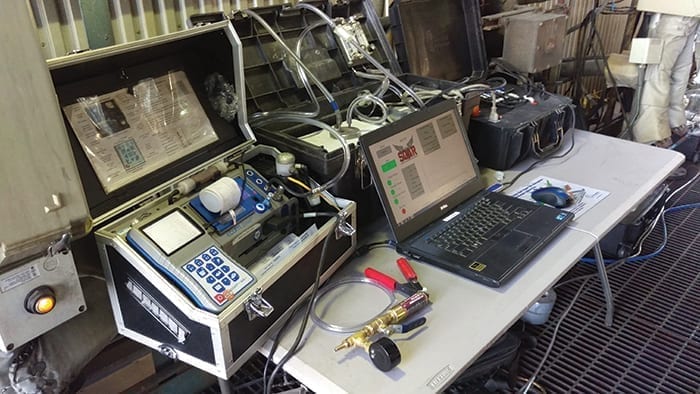
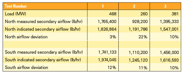
How can the airflow get this far off? There are three primary factors in Storm’s experience that lead to excessive amounts of airflow at lower loads. The first is a lack of accurate airflow measurement. Table 1 illustrates results from a total secondary airflow test on a 470-MW boiler. As you can see, the airflow indications are off an average of 13% at reduced loads, where the actual measured airflow is higher than indicated. Furthermore, one might note the inconsistency in the deviation of the north airfoil measurement between each test. This is indicative of a plugged/leaking airfoil or sensing line, which is very common to find when conducting this type of test.
 |
|
Table 1. Total secondary air test results. Courtesy: Storm Technologies |
Second, Storm has found that onsite plant engineers often prefer a little cushion, or a factor of safety, to be in place at minimum airflow, so they may increase the minimum airflow to 30% or 35%. But if you couple this with the fact that the airflow indication could be indicating 13% less airflow than actual, you can quickly end up at 40% to 50% of your total airflow at low loads.
Lastly, the ignitors, if in service, may have dark/hazy flames. The initial reaction from the plant may be to increase the airflow to the boiler, but as we will discuss in more detail in our fourth concern, this is not always beneficial.
Adding more air may not seem like such a bad idea when operators are focused on boiler combustion. However, too much air increases the boilers dry gas loss penalties, and if high enough, can require de-superheating spray flows at low loads, which is also a heat rate penalty. Furthermore, if the boiler is operating at 25% load, the differential pressure across the superheater is likely one-sixteenth of the full load differential pressure, and high amounts of spray water could result in plugging of superheater tube circuits, resulting in short-term overheating failures.
Poor Ignitor Flames
While starting up, shutting down, or when oil ignitors are put in service as supplemental firing for out-of-service pulverizers, ignitors are often found to suffer from “lazy” flame patterns. This is known to be the source of liquid oil carryover, elevated opacity levels, and has even caused air heater fires. The difference in the flame patterns and intensity seen in the before and after tuning pictures in Figure 5 were found to be a direct result of poor auxiliary air damper control, which was supplying a majority of the combustion air to the out-of-service burners instead of to the in-service ignitors. By adjusting the dampers and forcing the air to the in-service ignitors, the opacity was reduced from 40% to less than 5%, and the liquid oil carryover was eliminated.
 |
|
5. Poor ignitor flames (left) versus optimum flames (right). Courtesy: Storm Technologies |
More recently, Storm was involved with tuning of a circulating fluidized bed (CFB) boiler during startup. Prior to any adjustments, the boiler was operating with CO levels of 0.4 to 0.5 lb/MMBtu during startup, while utilizing as much as 3,000 gallons of oil. An array of issues was found regarding steam and oil pressure gauge measurements, but in the end, the total airflow supplied to the boiler was reduced 46.5% from the as-found flow, and distribution of the airflow between primary and secondary air was optimized. By improving the airflow distribution and control to the boiler, the plant was able to startup with more than a 50% reduction in oil usage and much improved CO levels (0.106 lb/MMBtu).
In closing, Storm Technologies’ objective in writing this article was to present four often-overlooked opportunities for improvement in operations flexibility that until recently were only experienced for short periods of time during startup but are becoming more common with PC boilers in today’s energy market. Today, coal plants are competing with non-dispatchable, must-run renewables, and therefore, they must become much more flexible in operations.
During 2018, the average electric power generation by coal fuel was 27.5% of the U.S. mix, according to the Energy Information Administration. However, the National Energy Technology Laboratory has found that during peak loads on the coldest days of winter, coal generation can be as high as 38% due to natural gas pipeline limitations, competitive generation costs, and operational difficulties of starting combined cycle gas turbine plants. That means coal power plant flexibility and reliability are as important as ever, not only for plant owners and operator, but also for national security and the well-being of customers. ■
—Shawn Cochran, PE is vice president of Field Services and Project Engineering with Albemarle, North Carolina-based Storm Technologies.