Coal Pulverizer Maintenance Improves Boiler Combustion
Optimized coal pulverizer performance is a prerequisite for ensuring the best furnace combustion efficacy. Here are some solutions for overcoming commonly identified combustion problems.
Coal pulverizers are the heart of a pulverized coal-fueled boiler. Often, the root causes of nonoptimized combustion lie with the pulverizers. Capacity; reliability; and environmental issues such as slagging, fouling, and higher-than-desired CO or NOx emissions; overheated superheater and reheater tube metals; and cinder fouling of selective catalytic reduction catalyst and air heaters have all, at times, been linked to poor pulverizer performance.
It is common in our experience to find pulverizers that are performing poorly, yet the degree to which unit reliability, efficiency, capacity, and environmental emissions are affected by them is often underappreciated. However, there are steps that can be taken to measure, quantify, and monitor pulverizer operation so that changes can be made to improve performance.
Measuring Pulverizer Performance
Obtaining representative samples of coal fineness and fuel distribution is the first step. The best method we have found to do this is by using an isokinetic coal sampler. All fuel lines must be sampled and the fineness sieved from each coal pipe separately. The fuel mass flow to each burner must also be measured.
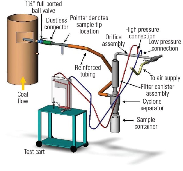
An isokinetic sampler similar to the one shown in Figure 1 can be used with a dirty-air velocity probe to establish the proper sample extraction rate. The fuel line velocities that are measured are used to compute the primary airflow and air/fuel (A/F) ratios of each coal pipe. The velocities and A/F ratios are valuable for diagnosing combustion issues.
 |
|
1. Isokinetic coal sampling. Getting accurate coal fineness, distribution, and flow measurements is the first step in optimizing coal mill/pulverizer performance. Source: Storm Technologies |
Tuning improvements can only be implemented after the true current performance is measured. Sampling single pipes, or sampling at a single location, is totally unacceptable in our experience. All fuel pipes must be sampled and sieved individually for best accuracy.
The fuel lines must be tested/sampled under normal operating conditions. Often during testing, we have observed that operating conditions are changed. For example, we have seen primary airflow reduced, classifiers reset for best fineness, and fuel flow brought back to mill design fuel flow rates. In other words, the assessment is not representative of normal operation. Testing under special conditions proves nothing. Only testing under normal operational conditions enables a useful diagnosis.
Out-of-Spec Results Are Common
Acceptable standards for best low-NOx burner performance are coal fineness of 75% passing a 200-mesh sieve and less than 0.1% remaining on a 50-mesh sieve. Fuel balance should be within the range of plus or minus 10%. However, in our experience, it is common to find fuel fineness that is well below 65% passing through a 200-mesh sieve and more than 1% remaining on a 50-mesh sieve. Furthermore, it is common to see fuel imbalances that exceed plus or minus 30% to the burners.
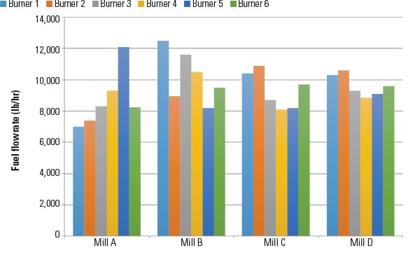
Figure 2 shows data from an actual test. In this particular case, the fuel had unacceptable fineness, which contributes significantly to poor distribution.
 |
|
2. Lopsided fuel distribution. This test data shows pulverizer fuel flow rates measured during an actual test. The fuel distribution is poor in this case. It should be balanced within plus or minus 10%. Source: Storm Technologies |
Once the data are compiled, out-of-specification readings must be investigated. An internal inspection should be completed to check the wear of grinding elements and classifier housings, vanes, and other internal components. Also, check for foreign matter that might be blocking fuel flow paths. Any problems identified should be corrected.
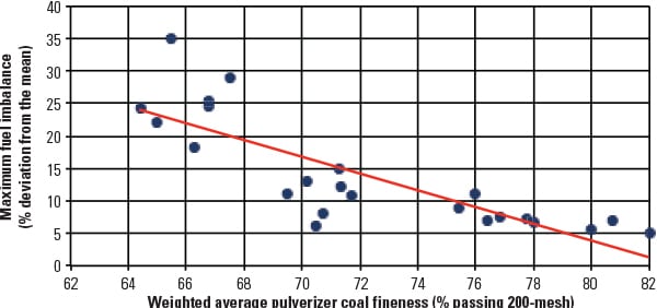
Achieving best fuel balance is done by first balancing the system resistance in all of the fuel lines using orifices and then increasing fuel fineness. Figure 3 shows the typical results of this approach to fuel balancing. Of course, internal pulverizer “blue printing” to best mechanical tolerances and optimizing an accurate and repeatable air/fuel ration is also important.
 |
|
3. Getting things back in line. This graph shows a typical relationship between fuel line distribution and coal fineness. Finer coal generally distributes more evenly. Source: Storm Technologies |
Pulverizer Mechanical Tuning Improvements Worth Considering
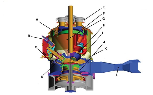
There are various adjustments and mechanical tuning measures that can be completed to improve the performance of a modern coal pulverizer. Locations identified on Figure 4 are keyed to the following improvements (journal pressures listed are for a #943-size pulverizer):
 |
|
4. Fine tuning. Getting tolerances back in specification by mechanically adjusting or replacing some components can greatly improve coal pulverizer performance. Source: Storm Technologies |
■ Install synchronized straight vane coarse particle guide blades (A). The retrofit lengthens the classifier blades, improves material to 3/8-inch-thick AR400 or better, and implements critical synchronization of the classifier blades for fuel/air two-phase mixture homogenization.
■ Increase journal preload (B) to between 36,000 lb and 42,000 lb (size appropriate loading).
■ Install rotating throats (C) to ensure proper velocity, improve primary classification, and reduce coal rejects.
■ Ensure optimum bullring and roll geometry (D) to achieve 1/4-inch roll-ring tolerances.
■ Install orifice housings (E) to support future balancing efforts. The change offers two advantages: It is easier for maintenance personnel to change out orifice plates, and it speeds testing and balancing efforts.
■ Install flared outlet cylinder extensions (F).
■ Repair all ceramic tile on the classifier cone (G) to ensure a smooth inner diameter.
■ Install three new, or three exactly matched, rolls (H) with similar 40,000 lb preload.
■ Verify that roll-to-ring clearances (I) are absolutely no greater than 1/4-inch over the full grinding length of the rolls and that the clearance is parallel to the bowl for the full width of the rolls.
■ Restore bowl angle (J) to the original design angle, typically 20 degrees plus or minus 1/2 degree.
■ Install designed throat deflectors (K) to improve primary classifications and to minimize issues with sand beds by vectoring airflow towards the bullring.
■ Relocate primary air thermocouple to venturi throat section (L), optimize insertion depth, and calibrate instrumentation more accurately.
Additionally, ensure that venturi sensing lines, connections, and transmitters are all in good condition. Tempering air dampers should be stroked and corrections made to ensure that they close at least 99%. This should also be done for hot air dampers.
All internal mill surfaces must be smooth so that the swirl of the coal/air mixture may enter and leave the classifier without spoiling or turbulence caused by double layer tiles, welded pad eyes, or other internal surface discontinuities. This, combined with precise primary airflow measurement and control, is important for uniform fuel distribution at the classifier outlet. All internal dimensions should be verified and technically directed by a qualified service engineer during installation of performance parts and before closing the mill.
Other Opportunities for Improvement
Overhauling Stock gravimetric feeders can also be worthwhile. The refurbishment should include calibrating load cells properly, installing modern microprocessors, adjusting belt tension appropriately, and completing accurate speed calibration.
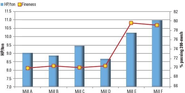
Another pulverizer performance monitoring technique is to observe the drive motor power input in correlation with the coal feed rate. The relationship of ton/hour to kWh power input is a very helpful leading indicator (Figure 5). A reduction in the power used by a coal pulverizer does not usually result in an improved heat rate. Instead, more grinding power nearly always correlates with better coal fineness. The only exception is with a ball tube mill.
 |
|
5. Mill power to ton of coal throughput. In general, when the mill draws more power per ton of fuel, it is an indication that finer coal is being produced. Source: Storm Technologies |
Getting Primary Airflow Right
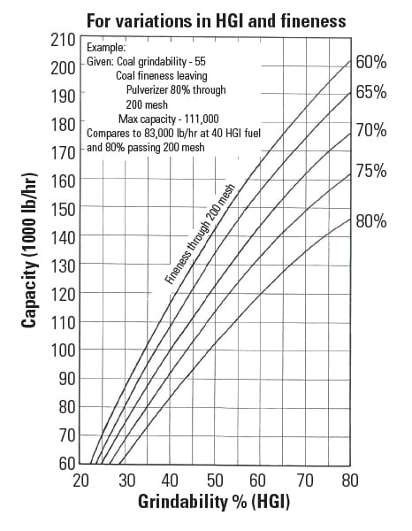
Pulverizer capacity is not simply a measure of coal throughput; capacity refers to a certain coal throughput at a given fineness, raw coal sizing, HGI (Hardgrove Grindability Index), and moisture. Often, if the desired coal throughput or load response is not achieved, the primary airflow will be elevated to higher flow rates than are best for capacity. However, increased throughput achieved in this way sacrifices fuel fineness (Figure 6).
 |
|
6. A negative correlation. The three main factors that constitute pulverized capacity are Hardgrove Grindability Index (HGI), fineness, and coal throughput. Increasing throughput will adversely affect fineness. Source: Storm Technologies |
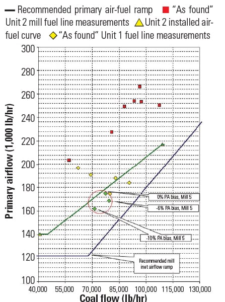
This is very common. When the primary airflow is higher than optimum, it creates entrainment of larger-than-desired coal particles leaving the mills, promotes poor fuel distribution, lengthens flames, and impairs low-NOx burner performance. We have found that targeting an A/F ratio around 1.8 lb of air per lb of fuel is best. For some pulverizer types, such as ball tube mills and high-speed attrition mills, often a 1.6 A/F ratio is optimum. Never have we observed good combustion conditions or good mill performance with A/F ratios of 2.5 or greater. However, it is common to find A/F ratios of 2.2 to 2.5 during baseline testing.
Results of as-found airflow to fuel flow testing from a sample plant are shown in Figure 7. In this particular case, the A/F ratios tested were well above the desired A/F ramp. When operators bias the primary airflow up, above the optimum, it may improve wet-coal drying, load response, and reduce coal spillage from the grinding zone, but it is not good for the furnace burner belt performance.
 |
|
7. Missing the mark. The air-to-fuel (A/F) flows shown in this graph are much higher than optimum. Installing properly sized rotating throats is often required to achieve targeted A/F ratios. Source: Storm Technologies |
All combustion airflow inputs should be measured and controlled, if possible. We prefer to use the tried and proven venturi or flow nozzles for this purpose because they are rugged, reliable, offer repeatable results, and are less prone to impulse line plugging.
MPS Mill Recommendations
Several components can be retrofitted to improve the performance of MPS mills. The changes may cost a significant amount of money, but the work will usually pay for itself through improved heat rate. One 450-MW coal-fired unit in the Midwest spent $750,000 on testing, changes, and tuning, but calculated that it saved millions by improving heat rate and by allowing higher-slagging fuel to be used at a reduced cost, which greatly increased its market competitivness.
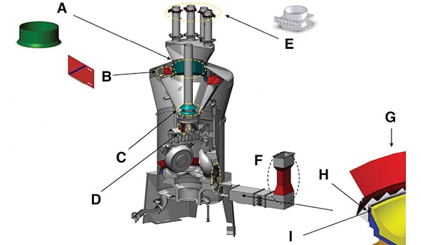
The locations corresponding to the following improvements are shown in Figure 8:
 |
|
8. Extending component lives. Getting 8,000 hours per year performance requires condition-based maintenance utilizing periodic isokinetic coal sampling and venturi hot “K” testing and calibration. Source: Storm Technologies |
■ Install an optimized outlet skirt component (A).
■ Install new optimized extended course particle guide classifier blades (B) for better classification and homogenization.
■ Set conical baffle (C) clearances and tolerances in accordance with optimized specifications.
■ Install optimized flapper/reject door (D) design.
■ Install clean air system resistance balance (E) with optimized orifice housings.
■ Retrofit primary airflow measurement device (F).
■ Install optimized deflector assembly (G).
■ Install optimized rotating throat assembly (H).
■ Add extension ring (I).
Cold air has a different density than hot air, which can result in a variance in measured velocity at similar mass flow rates. Because the K-factor will vary, we prefer to conduct “Hot-K” airflow calibrations that use typical operational air or gas density when developing an average K-factor. That information is important when developing a pulverizer primary airflow curve and when measuring all combustion airflows.
Most instrumentation technicians can calibrate and check using the “Hot-K” method to verify calibration accuracy. As previously mentioned, high primary airflows are one of the most common root causes of poor pulverizer performance, in our experience, so obtaining accurate and representative measurements is very important.
Getting the Best Burner Belt Combustion
The goal is to obtain the best possible burner belt combustion because it improves heat rate, reduces slagging/fouling, lowers emissions, and reduces cost. All of the following actions can help improve burner belt combustion:
■ Balancing airflow using fuel line orifice housings.
■ Retrofitting gravimetric coal feeders with new microprocessors and properly calibrated load cells.
■ Tuning pulverizers to tight mechanical specifications.
■ Maintaining a desirable A/F ratio of about 1.8.
■ Keeping pulverizer throat velocity within design parameters.
■ Calibrating flowmeters using the “Hot-K” method.
■ Checking fuel lines for fineness and distribution using isokinetic coal sampler testing.
Excellent pulverizer performance and fuel line balancing results in uniform flames in the boiler, which offers the following advantages:
■ Reduced CO and NOx emissions
■ Less slagging
■ Less fouling
■ Better fly ash loss on ignition
■ Reduced dry gas loss
■ Improved fuel flexibility
■ Reduced popcorn ash to the selective catalytic reduction system
■ Decreased furnace exit gas temperature
■ Less desuperheating water flow
■ Reduced sootblowing
With all of these benefits, it makes good sense to take action and implement changes that will improve plant performance.
— Richard F. (Dick) Storm, PE is senior consultant for Storm Technologies Inc. and a long-time POWER contributor. The staff of Storm Technologies contributed to this article.