Early detection of increased temperatures helps avoid power distribution asset-related failures and unplanned shutdowns. Wireless technologies make implementing this predictive maintenance solution practical and economical.
Electrical generation and associated high-voltage (HV) and medium-voltage (MV) distribution systems are critical infrastructure in power plants and other facilities. The crucial role of this infrastructure has garnered much attention and investment for improved monitoring (see “Facilitating Predictive Maintenance of Electrical Assets with Pervasive Sensing Strategies” in the April 2017 issue of POWER).
What has been overlooked to some degree is low-voltage (LV) power distribution at 600 V and below, which includes switchgear, power distribution units, motor control centers, and other critical LV electrical assets. These are present in virtually every industrial and commercial site.
LV electrical distribution has a history of under-investment, which leaves companies exposed to an ever-increasing risk of failures and unplanned outages—events that could be prevented with available monitoring technologies. Asset failures always prove costly to operators and are far costlier than implementing technology to provide continuous monitoring.
Owners and operators are painfully aware of both the hard and soft dollar costs associated with unplanned outages. Above and beyond the financial costs, failures introduce serious safety concerns and unnecessary risks for employees and asset operators, carrying intrinsic costs impossible to measure but very significant.
When considering the wide variety of LV asset types, the root failure modes of most equipment can often be predicted and prevented by monitoring a leading indicator, which is an unexpected increase in temperature most often caused by loose or failing connections, overloading, and corrosion.
Although LV asset issues left unidentified and untreated can result in final and sudden failure in the form of a flashover or a fire, the underlying cause typically progresses gradually over time. Traditional monitoring, if done at all, is periodic and often does not capture the slow progression to failure.
This article highlights the importance of monitoring these assets continuously, explains why temperature is the variable of concern, and describes how wireless technologies can provide the best temperature monitoring solutions.
Anatomy of a Failure
Electrical assets are designed and rated according to strict American National Standards Institute (ANSI) or International Electrotechnical Commission (IEC) specifications with specific operational parameters. Loose connections, improper contacts, and corrosion all reduce the current-carrying surface area, increasing heat buildup where contact remains. When this heat buildup exceeds the asset’s allowable temperature, larger breakdowns are set in motion.
In the least critical case, an overtemperature condition simply melts through without damaging other elements. However, the affected phase is effectively disconnected, resulting in a single-phase loss downstream. Of greater concern is when excessive heat migrates into conductors, eventually creating insulation damage leading to a phase-to-phase or phase-to-ground short circuit.
A loosening connection may become intermittent and produce arcing significant enough to affect nearby phases or grounded structures, initiating a short circuit. Arcing faults can create an extremely dangerous arc flash of highly conductive plasma as metal conductors are vaporized, creating a rapidly expanding explosive blast. The resulting shockwave contains molten metal and fragments, which can damage other parts of the equipment and injure nearby personnel.
Temperature Is the Key Indicator
Temperature is clearly a key variable for predicting impending failure. For this reason, some downstream equipment such as motors, UPSs, networking gear, and control panels may already include temperature monitoring, alarming, and interlocking.
But what constitutes a “good” temperature compared to a “bad” temperature? Simply taking a few temperature readings during a preventive maintenance cycle does not offer a complete picture, nor represent information in a useful context. It is instead much better to know temperatures at likely failure points when the equipment is energized and fully loaded.
For these reasons, temperatures must be monitored not only at peak load, but continuously. The loaded condition indicates whether the equipment is operating within safe parameters or not. With continuous monitoring this information can be stored and trended, which is the only way to reliably identify slow degradation over time.
Manual Inspection Difficulties
Manual inspections of LV assets are still valuable and necessary, despite introducing several difficulties. During a manual inspection, obvious symptoms such as burn marks may be observed, but underlying problems often remain undetected because they have not risen to the severity that displays obvious physical signs. This by no means suggests they are any less important to address.
Infrared (IR) inspection has been used to identify underlying issues in LV assets, even with energized equipment. However, IR inspection only works for line of sight, and it puts technicians at risk, placing them close to live equipment. Furthermore, IR inspection only measures emissivity and not the actual critical contact point temperature, and it doesn’t indicate how temperature is trending.
With these limitations in mind, continuous monitoring offers a superior solution. Continuous monitoring enables temperatures to be trended under all conditions, not just the electrical load and environmental conditions the day an inspection is performed. A continuous monitoring system can alarm if a high threshold is exceeded, and data from the system can be analyzed offline to evaluate equipment health over time.
Ambient temperature can be monitored alongside energized contact temperature in LV gear, and the temperature differential can be used to better understand normal temperature rise due to electrical current. Going one step further, loading data itself can be incorporated to get a much more accurate picture of asset health. Monitoring temperature, voltages, and currents together allows users to better understand if equipment has capacity for expansion.
SAW, NFC, and Wireless Solutions
Obtaining the temperature of an energized electrical component is not as simple as using a common thermocouple or resistance temperature detector because the sensor must achieve electrical isolation up to 600 V under Category IV or 1,000 V per IEC 610101-1. These standards also call for qualifying devices to withstand much higher short-term and impulse voltages, which is difficult or impossible with wired contact sensors. However, an alternate technology called surface acoustic wave (SAW) technology provides a viable solution. SAW sensors utilize acoustic wave signals, which are modulated by changes in ambient physical conditions, thereby providing a means to accurately and passively monitor local conditions.
Emerson Automation Solutions has developed a portfolio of compact SAW-based sensors under the IntelliSAW brand, which are targeted specifically for the very challenging and dense LV asset environment. This technology employs Integrated Near-Field Coupling (iNFC) to address these applications. Signals transmit wirelessly via iNFC across an insulated gap, achieving the required isolation. The product is wireless and passive, so it requires no maintenance in the form of battery replacement, and it contains no electronic components in the energized compartment that could fail.
 |
|
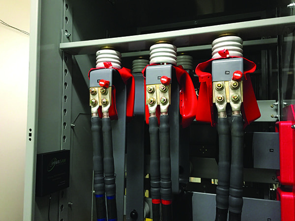
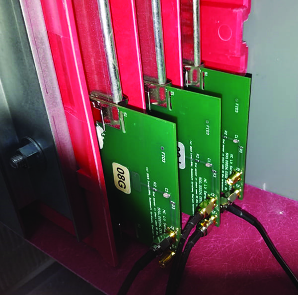
1. The clip-on sensor form factors shown here enable temperature monitoring of critical hot-spots at busbars. Courtesy: Emerson |
For maximum flexibility, several form factors are available. Two sizes of clip-on sensors accommodate busses (Figure 1), two sizes of three-pole sensors fit a variety of breaker and disconnect lugs (Figure 2), and a dual-cable version works with common parallel conductor configurations. Clip-on, cable tie, and bolt-mounted options facilitate installation in both new and retrofit applications (Figure 3).
 |
|
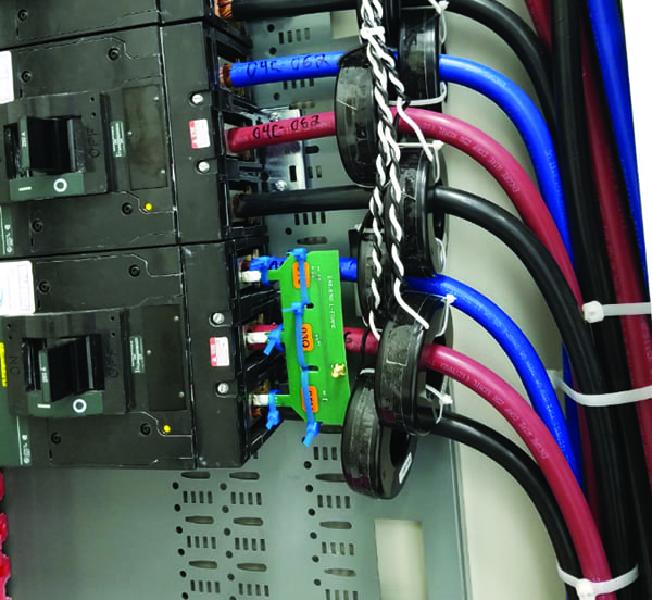
2. The three-pole sensor form factor shown here accommodates various sizes of circuit breaker and disconnect lugs, and is easily retrofitted using cable ties. Courtesy: Emerson |
 |
|
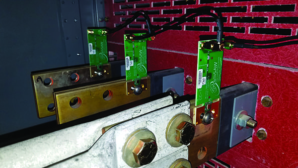
3. Bolted wireless temperature sensors, such as those shown here, are another option for both new and retrofit applications. Courtesy: Emerson |
While the use of coax cable to guide the radio frequency (RF) signals can make these sensors appear wired, it is important to remember that they actually operate at wireless frequencies across an electrically insulated physical barrier. RF cable runs are only necessary to promote a strong transmission signal and avoid any electrical interference concerns, typically being less than nine meters based on the geometry of the LV asset and the density of sensors.
Within an LV asset, up to 12 IntelliSAW sensors can be connected to one IRM-48 Reader monitoring unit, and up to 10 readers can be connected to one CAM-5 human-machine interface (HMI). Both the readers and the HMI use industry-standard communication protocols, allowing them to integrate into higher-level control systems and historians.
Application Example
A large financial institution operates multiple data centers across the country, and these centers support numerous financial transactions and customer interactions daily. These data centers are deemed mission-critical and rely on numerous, fully redundant LV assets to ensure reliable and conditioned power is delivered to thousands of servers.
During a recent manual inspection, operators smelled smoke due to electrical overheating and recommended an emergency shutdown, thereby reacting to an issue that had already escalated to a serious level. The unscheduled shutdown was prolonged as the operators struggled to identify the exact location of the trouble.
After this incident, the customer decided to install continuous monitoring for all its critical power distribution assets. IntelliSAW sensor systems were installed on the primary and secondary power delivery for their mission-critical servers to provide 24×7 data on asset health.
This data center now has continuous monitoring of the MV mains into the building, step-down transformers, LV switchgear, power distribution units, and automatic transfer switches. The site operators use real-time data to validate that electrical assets are operating normally and to schedule maintenance.
Peace of Mind
HV and MV power distribution has benefited by the addition of continuous asset monitoring technologies, allowing users to quickly detect impending trouble. The same business drivers and rationale apply to LV assets, and the technology is readily available and commercially proven. A key indicator of trouble is unexpected high or increasing temperature, which can be recognized and resolved early if a continuous monitoring system is in place.
Users with LV distribution assets at commercial and industrial facilities have typically relied on periodic manual inspections. But there is now a cost-effective, convenient, and safer way to implement continuous monitoring solutions in these assets utilizing SAW-based systems. Asset owner/operators who do so can feel confident that they have done everything in their power to maximize uptime and reliability for their customers. ■
—Jay Ganson is director of IntelliSAW products at Emerson Automation Solutions.