Long-distance conveyors are a reliable and energy-efficient method of bulk material transport. Pipe conveyors—fully enclosed material handling systems—offer additional environmental protection and more flexibility in passing difficult terrain by allowing smaller horizontal and vertical curve radii.
A 15-kilometer-long pipe conveyor near Hebi, China, was successfully commissioned in 2017. The conveyor carries 1,000 metric tons per hour (T/hr) of coal from the Yubei coal base to two 660-MW coal-fired boilers at the Hebi Heqi Power Plant. The system is the world’s longest single-flight pipe conveyor, surpassing the previous record of 8.2 kilometers (km) by a wide margin.
This article reviews some of the unique technical features of this conveyor system, including its low-rolling-resistance belt, light-weight elevated truss, self-powered maintenance trolley, and mid-booster drive design.
Pipe Conveyors
Pipe conveyors are a special type of belt conveyor. The belt is folded into a tubular shape with overlap by six idler rolls forming a hexagon. The main benefits of pipe conveyors are their ability to accommodate sharp curves and seal the transported material. The pipe belt encloses and separates the material from the environment. The pipe belt also has smaller area moment of inertia compared to a trough belt with the same width, which facilitates the bending of the pipe belt over horizontal and vertical curves. Over the last 15 years, pipe conveyors not only have more installations, longer conveyor lengths, and higher capacities, but also have gained better recognition among end-users in different industries as a feasible material-handling system.
The Yubei Coal Logistic and Storage Base is located in the northern part of the Henan province in China, near Hebi. The coal base is designed to handle 20,000,000 metric tons of coal per year and can store 800,000 metric tons of coal at any given time. It receives coal from nearby mines by rail and truck transport, stores and blends coal of different grades, and sends the coal to local consumers. About 7,000,000 metric tons are transported to two power plants, using a 30-km-long conveyor system.
The first 15-km conveyor—Yubei Section A—starts from the Yubei coal base and ends at the Fenghe Tongli Power Plant, which has two 300-MW and two 600-MW units. Yubei Section A has a design capacity of 1,850 T/hr. Some of the coal is consumed by the Fenghe Tongli Power Plant, and some is transported by a second 15-km conveyor—Yubei Section B—from the Fenghe Tongli Power Plant to the Hebi Heqi Power Plant.
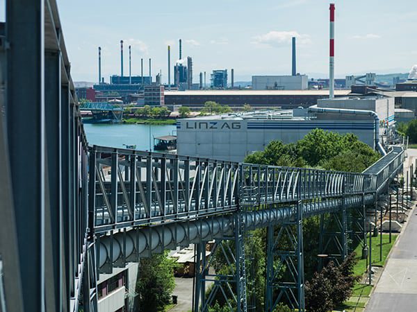
Yubei Section B has a design capacity of 1,000 T/hr. There are two 4,000-metric-ton silos between the Section A and Section B conveyors. Figure 1 shows the Section B pipe conveyor coming to the coal storage yard of the Hebi Heqi Power Plant. Yubei Section B was commissioned in 2017.
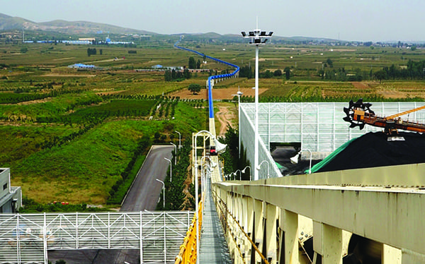 |
| 1. Beginning the trek. This image shows the head end of the 15-kilometer Yubei Section B pipe conveyor. Courtesy: Conveyor Dynamics Inc. |
Environmental considerations are an important factor in choosing the type of system to be used in coal-handling applications. The Yubei Section A and B conveyors cross some environmentally sensitive areas, including protected wetlands, natural parks, and rivers that provide drinking water. Several options for the Yubei material-handling system were evaluated in the project’s feasibility study.
One perception that has become more common among end-users and regulatory agencies is that the material should be separated physically from the environment, such as by using a totally enclosed material-handling system to ensure a clean material transport. By this premise, a trough belt needs to be placed in a totally enclosed structure, while a pipe belt can be placed in an open structure because the pipe belt itself is an enclosed material transport.
Normally, a pipe conveyor is more expensive in capital and operating cost compared to a trough conveyor; however, a totally enclosed conveyor structure is expensive. In addition, the pipe conveyor reduces the civil and land acquisition costs by allowing smaller curve radii and a more-flexible conveyor route. Combining these factors, a pipe conveyor was shown to have lower total costs for the Yubei project compared to a trough conveyor, and thus, it was chosen as the type of conveyor to be used.
Figure 2 shows the Section B conveyor profile in the elevation-view (top figure) and conveyor route in the plan-view (bottom figure). In Figure 2, the red line segments are the straight sections; the green line segments are the curved sections with 400-meter and 500-meter horizontal curve radii. The total length of the horizontal curves is 2.11 km—14.1% of the 15-km conveyor length. The total horizontal curve angle is 283 degrees. If a trough conveyor had been used, the total horizontal curve length would have required 8.4 km to achieve the same curve angle.
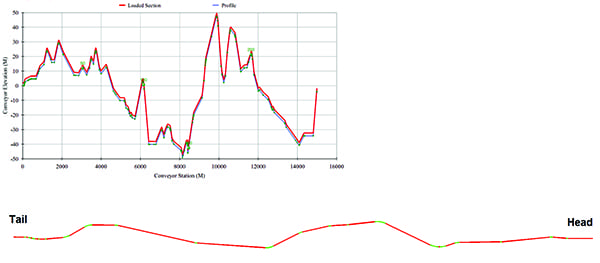 |
| 2. Up and down, back and forth. The graphs shown here depict the Yubei Section B conveyor profile (top figure) and conveyor route (bottom figure). Note: The elevation scale is different from the length scale. Courtesy: Conveyor Dynamics Inc. |
Initially, each of the 15-km pipe conveyors was divided into two individual conveyors with a length of about 7 km to 8 km, based on previously proven conveyor lengths, belt ratings, and drive sizes, among other things. However, Conveyor Dynamics Inc. (CDI) proposed a 15-km single-flight conveyor with a mid-booster drive for the Section A and Section B conveyors.
Figure 3 shows the schematic of the Section B conveyor’s drive arrangement. There are four drive points: head, middle, tail, and return-middle. Both the middle- and head-drive stations have two drive pulleys, each fitted with 1,250-kW motor driven by variable frequency drives. The return-middle drive has one 1,250-kW motor, and the tail-pulley drive has one 1,800-kW motor. The mid-drive station is 8.41 km from the tail loading point.
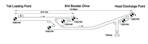 |
| 3. Driving the conveyor. This schematic shows the Yubei Section B conveyor drive and pulley arrangement. Courtesy: Conveyor Dynamics Inc. |
The drives at the different locations have different control methods. The drives at the head end are under speed control to maintain the designated belt speed. Load cells are installed at mid- and tail-drive stations to measure the belt tension, from which the control program regulates the drive torque output.
The design of long-distance conveyors with mid-drive systems has been successfully implemented in two previous CDI projects. One was the 20.3-km Curragh North trough conveyor in Australia, transporting 2,500 T/hr of coal and commissioned in 2007. The other was the 27-km Sasol Impumelelo trough conveyor in South Africa transporting 2,000 T/hr of coal and commissioned in 2015. Both conveyors became the world’s longest single-flight trough conveyors at the time of their commissioning. Compared to dividing one conveyor into two, the single-flight design with mid-drive has the following benefits:
- ■ It eliminates the take-up at the mid-transfer point.
- ■ It eliminates the surge hopper and simplifies the mid-transfer structure, because the belt is synchronized in starting and stopping. This also reduces the belt top-cover wear.
- ■ It has better dynamic behavior during the drift stop, where tension fluctuations caused by uphill and downhill sections are averaged by the longer belt length.
Indeed, the control engineering of multi-point drive arrangements is more complicated. But this can be addressed with sound engineering and a minor cost increase. The Yubei Section B pipe conveyor started the commissioning process in June 2017 and passed the full-load performance test in September 2017. CDI provided the basic conveyor, and structural and control design during the tender stage and project-execution stage for the primary engineering, procurement, and construction contractor Huadian Heavy Industries Co. Ltd.
Custom-Engineered Belt Solutions
CDI worked with belt manufacturer Zhejiang Double Arrow Rubber Co. Ltd. to develop a custom belt solution for the Yubei pipe conveyor system. The Section B belt is 1,500 millimeters (mm) wide with a tensile strength of 2,500 Newtons per millimeter (N/mm) and an 8-mm top cover and 6-mm bottom cover. The ST2500 belt has 95 6.7-mm-diameter steel cords. A faster belt speed—4.5 m/sec—is used to reduce the belt width from 1,600 mm to 1,500 mm to form a smaller 427-mm-diameter pipe to transport 1,000 T/hr of coal, which reduces the belt and structure costs.
A pipe belt’s cross-sectional stiffness and construction are critical to achieving the optimal conveyor performance. The folded pipe belt exerts contact pressure on idler rolls, which is strongly affected by the belt’s cross-sectional bending stiffness. The contact pressure, combined with the belt bottom cover, translates into the indentation rolling resistance (IRR).
The IRR is the hysteresis energy loss from the viscoelastic deformation in the belt bottom cover during the rolling contact with idler rolls. If the stiffness is too high, the pipe belt has very high IRR. It can even cause an empty belt to be unable to start. If the stiffness is too low, the pipe belt collapses and is not able to maintain the circular cross section. A collapsed pipe belt tends to have large rotation and twist in horizontal and vertical curves.
CDI has developed a pipe belt finite element analysis (FEA) program to analyze the pipe belt behavior. Figure 4 shows the full, three-dimensional FEA model of the Yubei Section B pipe belt. The belt deformation in horizontal and vertical curves is simulated to optimize the selected belt construction to reduce excessive pipe rotation and collapse. The pipe overlap opening between idler panels is modeled to fine-tune the belt construction to reduce the overlap opening.
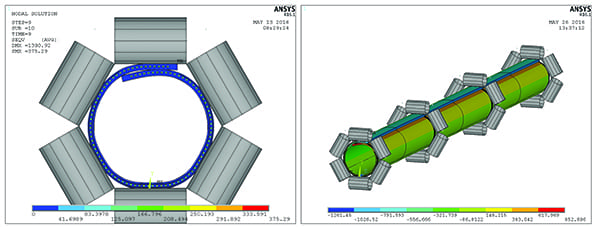 |
| 4. Rolling a pipe. This schematic shows the finite element modeling of the 1,500-millimeter (mm)-wide ST2500 pipe belt for the Yubei Section B conveyor, which formed a 427-mm pipe. Courtesy: Conveyor Dynamics Inc. |
Figure 5 shows three samples of folded pipe belts in a test machine that measures the six-point contact forces. There is one fabric layer in the top cover and one fabric layer in the bottom cover. The two fabric layers have different widths to provide sufficient cross-sectional stiffness while maintaining a flexible and tight overlap seal. The three samples have different fabric type, width, and cross-sectional stiffness, which resulted in different pipe shapes.
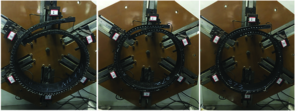 |
| 5. Theory to practice. Different belt construction and stiffness results in different pipe shapes. The images shown here demonstrate how various fabric types, belt widths, and cross-sectional stiffnesses affect pipe formation in a test rig. Courtesy: Conveyor Dynamics Inc. |
The pipe cross-sectional stiffness is characterized using a three-point bending test. The test sample size is 312 mm wide and 51 mm long cut from the center and edge area. The belt stiffness measured from the three-point bending test is much more sensitive to changes in the belt construction than the ISO 703 troughability test.
For every 5% change in the troughability value, there is approximately 25% change in the three-point bending stiffness value. The more sensitive three-point bending test provides higher accuracy and better control of the belt stiffness. In addition, a bending fatigue test is also done on the full-width pipe belt sample to verify the stiffness decay after 350,000 cycles of pipe opening and closing.
A pipe belt’s power consumption is an important aspect of the belt design. It has been shown that the IRR from the contact between the belt and idler roll can account for about 60% of the energy loss in an overland trough conveyor. A low-rolling-resistance (LRR) belt has a modified bottom-cover rubber with less hysteresis energy loss and less IRR, which reduces power consumption and belt tension, especially for long-distance overland conveyors. This means smaller drive sizes and a reduced belt rating can be used, decreasing both capital and operating costs. Less belt tension also improves the conveyor’s starting and stopping dynamics, increases splice life, increases idler and pulley life, and reduces pipe belt deformation and rotation.
There are multiple methods to test and quantify the IRR. CDI uses a dynamic mechanical analyzer (DMA) to measure rubber’s viscoelastic property and then uses a proprietary in-house program to calculate the associated IRR. The pipe belt’s contact pressure on six idler rolls is exported from the finite element model and imported into Beltstat conveyor-design software, along with rubber DMA test data, to do static and dynamic analysis. Fire-resistant belt is generally required by end-users for coal handling. As such, CDI specified a fire-resistant, LRR belt in the conveyor design to improve the conveyor performance. Extensive testing and compounding efforts have been undertaken to develop a rubber compound that meets the LRR, fire resistance, and other requirements like strength, abrasion, and ozone resistance for the pipe belt.
Elevated Truss with Vehicle-Based Trolley
The end-user required the Yubei pipe conveyor system to be elevated six meters above ground by a truss structure. An elevated conveyor reduces the interference with local residents and improves safety. In such cases, a walkway is usually required on the side of the truss to provide access for conveyor maintenance and inspection. But in this project, the walkway was replaced by a moving trolley vehicle.
There are multiple benefits to this approach. Firstly, structural weight and capital costs are reduced. Typical double-side walkways weigh about 100 kg/m. Structural design standards typically mandate 2,000 to 3,000 N/m2 live-load on the walkway. Rarely is the conveyor walkway subject to such heavy loads, but the truss structure has to comply with the governing structural standard. The walkway weight and load requirements add additional weight to the truss. Secondly, the truss span can be increased due to lighter weight. Increased truss span reduces the total number of support columns and associated civil costs. Thirdly, maintenance and inspection of long-distance conveyors are much more efficient and convenient using the moving trolley.
CDI’s first project of this kind was the 6.9-km Dangote Obajana limestone conveyor in Nigeria, commissioned in 2007. The 2,500 T/hr trough conveyor was elevated six meters above ground by a triangular truss without a walkway. The truss span between support bends was 36 m. A custom-designed, self-powered trolley travels over the triangular truss for inspection and maintenance. By 2015, the moving trolley designed by CDI had been successfully implemented in five different projects (the 6.9-km Obajana Line 2, the 7.7-km Obajana Line 3, the 10-km Obajana Line 4, the 3-km India Dahej, and the 5-km Nigeria Ibese). In the Yubei Section B pipe conveyor, the savings in structural steel by eliminating the walkway was about 150 T/km. For the entire 15-km-long conveyor, the total saving was 2,400 tons of steel.
The box truss is made from hot-rolled angle and channel steel sections, while the triangular truss is made from seamless steel pipes. Steel pipes have superior load bearing capacity compared to angle and channel steel sections but are more expensive. The box truss has 30-m spans at the straight and vertical concave curve sections, shown in Figure 6, while a conventional box truss with walkway typically has 25-m spans.
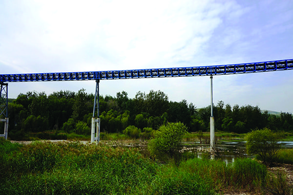 |
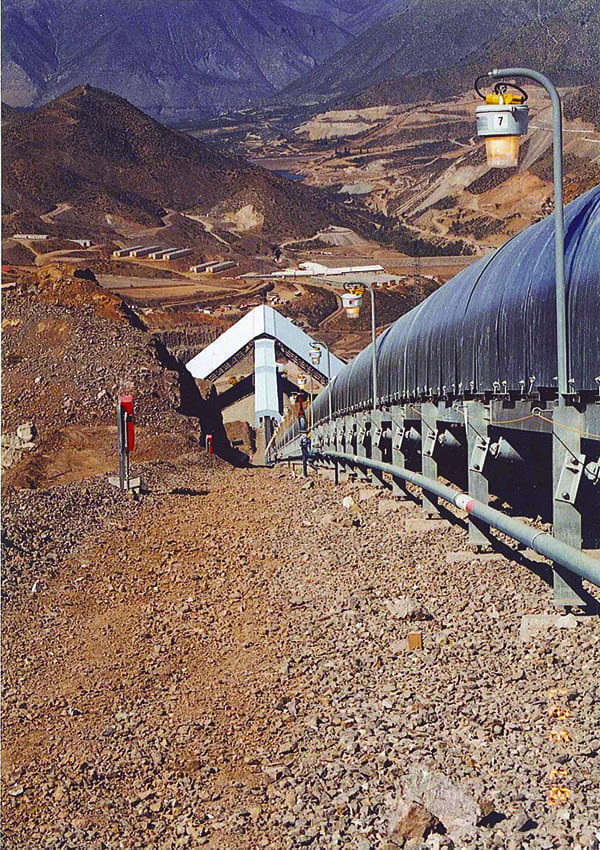
| 6. Maximizing span minimizes steel. This image shows a 30-m span between trusses of the Yubei Section B pipe conveyor crossing a protected wetland. Courtesy: Conveyor Dynamics Inc. |
A small four-wheel-drive truck was modified to include work platforms on both sides and special structures for the vehicle to run on the box truss. The box truss is more suitable for vehicle-based trolley use, while the shape of the triangular truss requires a custom-designed trolley structure. Figure 7 shows the maintenance vehicle on the Yubei conveyor truss. The vehicle provides a capable drive unit and light-body frame, compared to a custom-designed trolley. Another innovation on the Yubei maintenance vehicle is that it is equipped with a radio transmitter to send emergency-stop signals to the conveyor’s control system, which replaces the pull cord along the entire length of the conveyor.
 |
| 7. Innovative access. A small four-wheel-drive truck was modified to include work platforms so maintenance and inspections could be easily performed on the Yubei Section B pipe conveyor, which eliminated the need for walkways on the sides of the trusses. Courtesy: Conveyor Dynamics Inc. |
Commissioning and Performance
The commissioning process of the Yubei Section B conveyor started in June 2017 and concluded with the completion of full-load performance tests in September. The commissioning time was short considering the length of the conveyor. Minor belt training was done but no extensive effort was needed to correct any large rotation.
The pipe belt maintains full contact on six idler rolls in straight sections and has small deformation in curved sections. The LRR pipe belt achieves the predicted savings in power consumption. In fact, the power consumption is close to the low-friction condition calculated in the conveyor analysis, lower than the normal or high-friction condition that was expected to occur during the initial operation of the pipe conveyor. Figure 8 shows the conveyor power consumption at the empty and full-load condition.
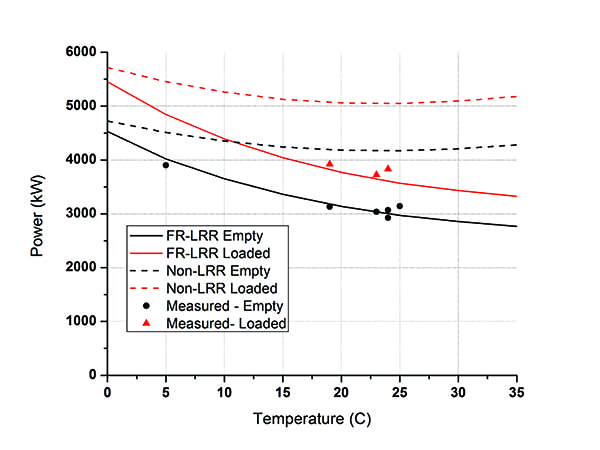 |
| 8. Power consumption. The graph in this figure shows the calculated and field-measured power consumption for the Yubei Section B pipe conveyor. The fire-resistant (FR) low-rolling-resistance (LRR) belt proved to offer significant savings compared to non-LRR belt materials. Courtesy: Conveyor Dynamics Inc. |
The figure also shows the comparison between the calculation and the field measurement. The black and red solid lines are the calculated power-temperature curves for the empty and fully loaded belt, respectively, running at full speed. Both solid lines are calculated from the measured pipe belt stiffness and rubber viscoelastic properties. The black circles are the measured power consumption from the empty belt. The red triangles are the measured power consumption from the fully loaded belt.
Indeed, the LRR belt reduced the power consumption as expected. At 20C, the LRR belt reduces energy consumption by 25% compared to a regular rubber belt; at 30C, the LRR belt’s energy savings increased to 30%. If using a regular, non-LRR pipe belt, the power consumption from the empty and fully loaded pipe belt was calculated to follow the black and red dashed line, respectively.
The difference becomes larger at warmer temperatures. Assuming 25% reduction in power consumption, total annual energy saving for transporting 4,000,000 tons of coal is more than 5.1 GWh. This energy savings not only reduces the operating cost but also reduces the annual greenhouse gas emissions by approximately 3,800 metric tons of CO2, according to U.S. Environmental Protection Agency models. ■
—Yijun Zhang PhD, PE is technical director with Conveyor Dynamics Inc.