Experience gained by a project team during a steam blowing operation for a combined cycle power project in Indonesia is described in this article. A specific challenge faced by the commissioning team is explained, along with the solution used to successfully overcome the obstacle.
A steam blowing operation is one of the critical pre-commissioning activities carried out in new power projects where construction is completed, and the commissioning phase is ongoing. This activity is performed on the critical steam piping of the steam cycle circuit to ensure that any scales, oxides of metal, and slag left behind in the piping internals during the welding process are removed prior to initiating steam turbine operation.
The steam cycle circuit typically refers to all the piping that is connected between the heat recovery steam generator (HRSG) and the steam turbine. This is an important activity to be completed by the engineering, procurement, and construction (EPC) contractor as part of steam turbine original equipment manufacturer (OEM) start-up requirements. Otherwise, any leftover metal particles or scales formed within the pipes can travel along with the steam into the steam turbine and can cause pitting/damage on the turbine blades. In some cases, the damage can be catastrophic in nature. The criteria or guidelines for cleaning the steam piping are set by the steam turbine OEM and need to be fulfilled by the EPC contractor.
The experience gained by a project team during the steam blowing operation for a combined cycle power project is described in this article. The details of the steam blowing procedure (such as calculations, construction details, step-by-step sequence, and methodology to execute the steam blowing procedure) are not covered in this article. Rather, the focus is drawn more toward challenges faced during execution of the SBO at the site and solutions used to overcome the difficulties. To understand the necessity of this procedure in detail, readers should review literature available in the public domain. Another source to help understand the guidelines is VGB PowerTech, an international association of energy plant operators based in Germany. Among its guidelines is VGB-R 513 e “Internal Cleaning of Water-Tube Steam Generating Plants and Associated Pipework.”
The Indonesian Plant Design
Tata Consulting Engineers Ltd. (TCE) was retained as the engineering consultant for detailed design and engineering services of a combined cycle project in Indonesia (Figure 1). The plant was commissioned in December 2018 and is currently in commercial operation.
 |
|
1. This is a night-time view of the heat recovery steam generators (HRSGs) and stacks at the plant in Indonesia. Courtesy: Tata Consulting Engineers Ltd. |
The project comprises a combined cycle power block (2-2-1 configuration) with a gross rated output of 500 MW. The block was added as an expansion project to an existing plant. It consists of two gas turbines (GTs) and generators, two HRSGs, and one steam turbine and generator (STG) in multi-shaft configuration with bypass stack (which allows simple cycle operation) and balance-of-plant (BOP) equipment.
The GTs are designed for single firing using natural gas. Each GT is coupled to a dedicated HRSG unit that produces high-, intermediate-, and low-pressure (HP, IP, and LP) steam from the thermal energy in the GT exhaust. The steam generated by each HRSG in a block is combined in a common steam header and delivered to a common steam turbine (ST), thereby allowing the ST to generate power in a bottoming cycle. The ST is a reheat condensing turbine. The exhaust steam is condensed in a water-cooled condenser, and the cooling system for the steam turbine condenser is once-through cooling using seawater drawn from an intake canal.
The GT is an advanced E-class heavy-duty gas turbine designed for 50-Hz operation with single shaft, cold-end drive and silo-type combustors. The HRSG is a horizontal type, natural circulation, unfired, reheat, triple-pressure design. The low-pressure drum of the HRSG is provided with a feedwater storage function and the integral deaerator is mounted on top of the LP drum. The condensing steam turbine consists of HP and IP-LP cylinders for steam expansion.
The Steam Blowing Process
During the steam blowing operation (SBO), the steam is generated in the HRSG at low pressure and a huge volume of steam flows at high velocity thru the critical piping that connects the HRSG to the steam turbine. The critical piping is typically the HP steam lines, cold reheat (CRH), hot reheat (HRH), HP steam bypass lines to cold reheat, low-pressure lines connected to the LP portion of the steam turbine, and HRH/LP bypass lines to the condenser. The ST does not participate in the SBO process and is isolated until the SBO is completed. Temporary piping is used to interconnect these lines so that the connectivity and flow are established while this major piece of equipment is isolated.
When steam at high velocity is passed through the piping, scales and small particles that are stuck to piping internals are carried away by the steam, thereby cleaning the piping internals. The steam, after traveling through the piping, is finally vented out to atmosphere (Figure 2).
 |
|
2. This image shows steam being vented through a silencer installed in the steam turbine area during the steam blowing operation. Courtesy: Tata Consulting Engineers Ltd. |
The bypass lines are service blown until the steam vented to atmosphere is visually clean, whereas the HP, CRH, HRH, and LP lines are target blown, that is, target plates are used to check the cleanliness of these pipes. The target plates are inserted in the temporary steam blowing pipes. Scales and any foreign particles removed by the steam hit the target plate and create pits. A high number of pits and/or larger-sized pits in the target plate indicate poor piping cleanliness. With repeated blows, the size and number of pits on the target plates are gradually reduced to minimal.
The allowable final size and number of impacts/pits measured per square inch of the plate is decided by the STG manufacturer. After meeting this criterion, the steam blowing activity for the respective piping circuit is deemed complete and qualified for commercial operation. The steam blowing operation is normally carried out in a sequential process, blowing all the identified critical lines one after the other.
The Steam Blowing Operation
Based on recommendations from the ST manufacturer, the continuous blowing method was implemented in this project. During SBO, adequate cleaning force ratio (CFR) across the steam blowing circuit must be ensured. CFR is defined as follows:
CFR = (mb2 × vb) / (mo2 × vo)
where mb is the mass flow rate of steam during steam blowing, mo is the mass flow rate of steam during normal operating condition where momentum is maximum, vb is the specific volume of steam during steam blowing, and vo is the specific volume of steam during normal operating condition where momentum is maximum.
To ensure proper cleaning of critical piping, a CFR of ≥ 1.2 was followed in accordance with VGB-R 513 e guidelines. This criterion ensures that the cleaning will be accomplished by generating steam velocity in the pipeline that is greater than what typically occurs in each steam line during normal operation.
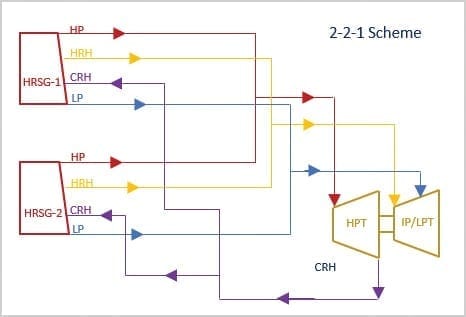
In a 2-2-1 configuration, the typical piping arrangement is such that individual lead lines (HP, HRH, CRH and LP) from one HRSG are tied to respective lead lines from the other HRSG at a certain distance to form a header line. The header line is routed down to the steam turbine inlet. The outlet piping from the HP steam turbine is a header that is again branched out to individual lead lines returning to individual HRSGs. The header lines are sized bigger when compared to individual lead lines. Figure 3 indicates a typical scheme of piping connection between HRSG and ST.
 |
|
3. A typical piping scheme for a 2-2-1 combined cycle gas turbine configuration with HRSGs; high-, intermediate-, and low-pressure (HP, IP, and LP) turbines; hot reheat (HRH); and cold reheat (CRH) lines shown. Courtesy: Tata Consulting Engineers Ltd. |
The Challenge
In this project, the material selected for the HP and HRH individual lines and header, as well as for the steam bypass lines to the condenser, was alloy steel. During the design stage, the outlet steam parameters for different operating conditions at the HP steam turbine exhaust were evaluated and carbon steel piping was selected for the CRH line (header and individual lines to each HRSG). The decision to select carbon steel material for the CRH lines led to challenges during the SBO.
While blowing the headers, both the gas turbines and their respective HRSGs were operated to achieve the desired CFR. However, the CFR in the individual CRH and HRH lead lines could not be achieved in this mode for two reasons. First, the normal operating pressure in the lead lines is lower during 1-1-1 operation, which results in a higher specific volume of steam, and subsequently, maximizes momentum conditions (mo2 × vo). Second, operating both GTs at the same time during steam blowing results in higher steam flow through the piping. This results in increased pressure drop across the piping. As the pressure drop is higher in the steam headers and temporary piping, the steam blowing pressure at the individual lead lines is also expected to go up. This results in lower specific volume of steam, and in turn, leads to lower CFR values.
Therefore, to achieve the required CFR in the individual CRH and HRH lead lines, only one train was operated (one GT and one HRSG). While increasing the GT load to meet the CFR requirement, it was observed that the main steam temperature was rising close to 500C, which is not acceptable for carbon steel piping (CRH lines). The acceptable temperature limit for carbon steel piping is 427C.
One option to bring the temperature of the steam down to an acceptable level was to add an external desuperheater, upstream of the CRH line. This would spray water in the steam prior to admitting it into the CRH line to bring down the temperature to the desired level. However, a desuperheater was not anticipated during the design stage. Considering that the project was in the commissioning phase, procurement of a desuperheater would have delayed the process, as this item was not readily available in the local market and had to be procured and shipped from a neighboring country. Furthermore, piping erection was also completed at site and adding a desuperheater at that point would have been complicated and resulted in a schedule delay. Hence, this option was ruled out.
During the design stage, an intermittent type of blowing was proposed to the STG manufacturer. However, the STG manufacturer later insisted on following the continuous blowing methodology to meet its requirements. Considering the shortage of time available and to avoid any schedule delay, the only option was to successfully execute the continuous steam blowing operation with the existing design.
The Solution
The root cause of the problem was high-temperature GT exhaust gases that in turn produced high-temperature steam while trying to achieve the required CFR values. This had to be brought to a permissible level for the carbon steel CRH piping. All the other critical lines identified for steam blowing were alloy steel piping, and hence, the higher temperature was acceptable.
The GT is the main driver that increases the temperature of the steam while increasing the load. The key requirement to meet targeted CFR values was increased mass flow of steam at desired lower temperatures acceptable to carbon steel piping. To increase the mass flowrate of steam, the GT exhaust gas mass flowrate must also be increased, which is possible only when the GT load is increased. Subsequently, the GT exhaust gas temperature also rises to undesirable levels.
If the exhaust gas temperature is controlled from the GT side, then subsequently, the temperature of the steam is also brought down to acceptable levels. Based on discussions with the GT manufacturer, it was understood that the turbine exhaust temperature (TET) could be brought down by pre-setting the value in the GT control system to the desired temperature at rated GT exhaust flow condition. This could temporarily be modified to meet the steam blowing requirements, and then be reset to the normal operating conditions at a later stage. Achieving the desired lower temperature without software modification was not possible.
GT in Normal Operation Mode. The gas turbine is operated in such a way that the temperature remains constant up to full-speed no-load (FSNL) conditions. After synchronization and as GT load gradually increases, the exhaust temperature also rises and reaches rated temperature (550C) between 50% and 60% of the GT load. The inlet guide vanes (IGVs) are in tracking mode and follow GT loading beyond this point. The IGVs start to open up gradually, thus increasing the mass flowrate to rated conditions. The fuel supply is also increased in parallel, such that the exhaust temperature remains at rated temperature until the gas turbine reaches full load.
GT in Steam Blowing Mode. In this mode, the TET is pre-set to the required temperature by modifying the GT control software. The gas turbine operation is initiated. There is no change in the operation until the GT reaches FSNL. After synchronization, the exhaust temperature is controlled to the pre-set temperature as the GT continues to load further. The exhaust mass flowrate continues to increase, while the modified TET continues to remain constant until the rated load is achieved.
 |
|
4. This graph shows the gas turbine (GT) exhaust gas temperature profile. Load, turbine exhaust temperature (TET), modified TET, and exhaust mass flowrate (Mexh) are indicated in percent on the y axis. Time after synchronization is shown on the x axis in seconds. Courtesy: Tata Consulting Engineers Ltd. |
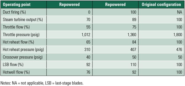
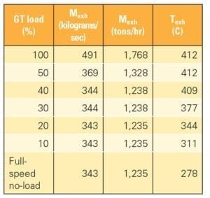
Figure 4 illustrates the normal and modified GT exhaust gas temperature profile for both of the above described modes. The variation of GT exhaust gas temperature and mass flowrate for varying loads during Steam Blowing Mode is indicated in Table 1.
 |
|
Table 1. Variation of GT exhaust gas temperature and mass flowrate in Steam Blowing Mode. Source: Tata Consulting Engineers Ltd. |
The key was to maintain the GT exhaust temperature at a pre-set desired level and continue increasing the mass flowrate so that the mass flowrate of steam generated will also increase. This will ensure that the desired steam flowrate at the lower temperature is generated, and hence, CFR requirements for the HRSG lead lines are met.
Any risk on operating the gas turbine under Steam Blowing Mode was also evaluated. Considering that it is a heavy-duty gas turbine, it was understood from the OEM that it could be operated in this mode temporarily for a limited period.
Prior to implementing the above modifications in the GT control systems, the proposed revisions in the software underwent various tests (using the simulator) to understand any other issues that may come up while operating the GT under this mode. It was observed that there were no errors or alarms generated during the simulations. The next step was to implement this modification in the GT control systems.
The Result
After modifications, two options were available in the GT control system when the GT reaches FSNL conditions. They are: GT in Normal Operation Mode and GT operation in Steam Blowing Mode. Steam blowing was successfully completed using the modified approach, with the GT operating under Steam Blowing Mode. The steam blowing mode in the GT control system was made inactive after completing the operation.
The procedure adopted in this project is applicable for the continuous steam blowing methodology. The decision to select the method of steam blowing depends on the ST manufacturer’s recommendation.
The above technique of executing the steam blowing operation is not the conventional method practiced in the power industry. This method is the result of addressing a unique challenge encountered in this project.
While the situation encountered in this project was challenging, the methodology adopted to resolve it has opened the door for cost avoidance in future projects. If the above methodology is planned and executed from the project initiation stage, there is a good chance for the EPC contractors to save money on the piping material for the CRH line and other temporary piping. It is understood that this methodology of steam blowing is more appropriate in combined cycle projects where E-class and advanced E-class GTs are selected for the topping cycle.
However, engineers must carefully review different operating conditions of the steam turbine and analyze the steam temperatures at the turbine exhaust before deciding to implement this methodology. If the steam temperature at the HP turbine exhaust for different operating conditions is ≤400C, then it is possible to select carbon steel piping for the CRH line and other temporary piping. Further, the requirements of operating the GT in Steam Blowing Mode need to be clearly stated to the GT manufacturer in the initial stage of the project and the feasibility of the same needs to be evaluated jointly. In a scenario where the proposed modification is not agreeable to the GT manufacturer, the following two methods can be explored:
- ■ Intermittent type of blowing (in consultation with the STG manufacturer).
- ■ Adding an external desuperheater in the temporary piping.
Intermittent blowing increases the commissioning duration by several weeks. In case of selecting an external desuperheater, the main challenge would be to address the limited space below the STG deck for installation of temporary piping along with the desuperheater. Also, this option would increase the commissioning cost due to the addition of the desuperheater, control valves, instruments, cabling, spray water piping, and alloy steel piping upstream of the desuperheater.
To understand the scope of savings, a quick calculation was made to compare different materials for piping. In this project, it was observed that if alloy steel was selected instead of carbon steel for the CRH piping (excluding other temporary piping used for SBO), the additional cost to be incurred would have been about $250,000. Based on the experience gained in this project, the new option can be explored in future projects for implementation, and thereby, potential savings may be realized and/or longer commissioning periods avoided.
—Rajarajan Rathina is deputy general manager and Senthil Rajendran is senior manager for Tata Consulting Engineers Ltd.’s Power Business Unit.