SaskPower's Boundary Dam Carbon Capture Project Wins POWER's Highest Award
Courtesy: SaskPower
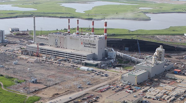
There was no debate among our editorial team when it came to selecting the most interesting and worthy project worldwide for this year’s top award. Boundary Dam Power Station Unit 3 is the world’s first operating coal-fired power plant to implement a full-scale post-combustion carbon capture and storage system. It did so more economically than other commercially available capture processes, and the utility has been active since project initiation in sharing its experience with generators, regulators, and others globally.
[Access a full-screen version of this story.]
The 2015 POWER Plant of the Year award goes to a single, relatively small coal-fired unit: Boundary Dam Power Station Unit 3 (BD3) and its integrated carbon capture (CC) plant. But the award really goes to SaskPower, the Saskatchewan provincial utility that owns the unit, for developing an entire carbon capture and sequestration (CCS) infrastructure and larger ecosystem to support that unit.
The magnitude of the need to lower greenhouse gas (GHG) emissions in order to limit the negative consequences of climate change has led many jurisdictions around the world to set GHG reduction goals and to adopt policies that place limits on emissions from new and existing coal-fired power plants. For example, Canada in 2012 passed legislation at the federal level requiring new coal-fired plants to include carbon capture and requiring existing plants reaching the end of their useful life (defined as 50 years) to shut down unless they are retrofitted with CC facilities. But even before then, Ontario decided to eliminate coal-fired generation (see “Ontario Goes Coal-Free in a Decade” in the May 2013 issue or in the archives at powermag.com), and SaskPower had already committed to its BD3 project.
Whereas some jurisdictions are striving to reduce emissions by replacing fossil fuels with renewables or nuclear power, others (typically, those with fossil fuel resources) are hoping that CCS technologies will enable the continued use of abundant and relatively affordable fossil fuel resources while keeping climate-forcing carbon dioxide (CO2) out of the atmosphere.
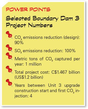
It’s true that equipping one 161-MW gross coal-fired unit with 90% carbon capture is a small step in the global context, but it’s also true that someone had to take it. The SaskPower team has taken what actually constitutes a giant leap for the coal-fired power industry and, consequently, has garnered attention from around the world.
I was fortunate to visit Boundary Dam Power Station (BDPS) and interview some of the project leaders in mid-May. The professionalism displayed by everyone I met is clearly one reason this project reached completion in a timely way and with minimal cost overruns.
Plant History and Location
SaskPower is a government-owned utility that provides power to the majority of the province of Saskatchewan and manages approximately C$9 billion (US$7.36 billion) in generation, transmission, and distribution assets. It operates three coal-fired power stations, seven hydroelectric stations, six natural gas stations, and two wind facilities, and has partnerships with 21 independent power producers for a total capacity of 4,211 MW. (A note on costs and currency conversions: All dollar amounts are in Canadian dollars unless otherwise noted. Though the Canadian dollar was at and above parity with the U.S. dollar in 2011, when construction began on the CC facility, in mid-June 2015, as this article was being finalized, the Canadian dollar was worth about 82¢ U.S.)
BDPS is the largest facility in the SaskPower fleet and is located near Estevan, roughly a dozen miles north of the U.S.-Canada border. Construction on the six-unit plant began in 1955, and it has been generating power since 1959. Units 1 and 2 were retired in 2012 and 2013 because they were small, 65-MW, inefficient, non-reheat units that were reaching the end of their life, and the decision was made to not upgrade them in light of federal regulations requiring plants older than 50 years to either add CCS or shutter. The remaining units (3 through 6) total 750 MW. The plant is divided into A (Units 1 and 2), B (Units 3 and 4), and C (Units 5 and 6) units, each with its own control room. Staff from Units 1 and 2 were reassigned and “instantly absorbed” mostly into B, especially with the Unit 3 and 4 overhaul, explained Scott Walton, Unit B production manager.
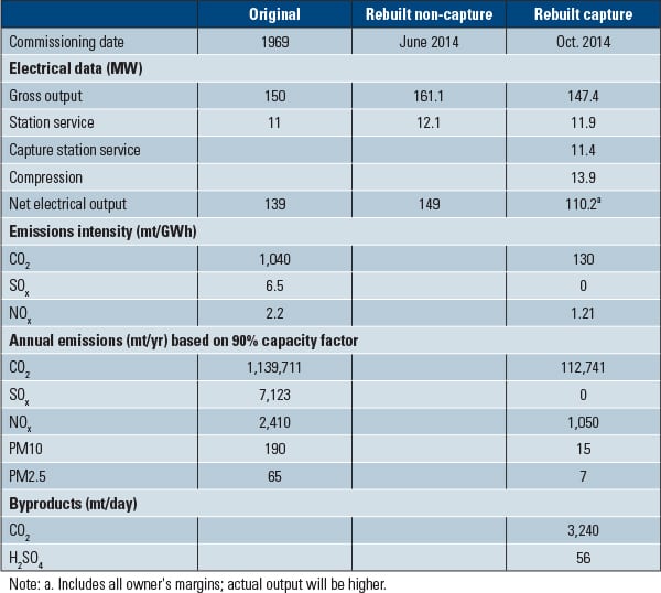
Unit 3 came online in 1969 as a 150-MW unit; after the recent turbine replacement and CC integration, it is rated at 161.1 MW gross/110.2 net, after accounting for parasitic load, primarily for the CC process.
Unit 3 consumes over 800,000 metric tons (mt) of coal per year, provided by the Estevan Mine, operated by Westmoreland Coal Co. The open pit mine, located about 8 miles from the plant (Figure 1), has been operating since 1905.
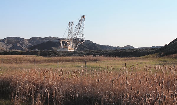 |
| 1. Local lignite. This open pit mine is less than 10 miles from Boundary Dam Power Station. Coal is trucked along access roads to the plant. Source: POWER/Gail Reitenbach |
The plant is located adjacent to the Boundary Dam Reservoir Recreation site and uses the reservoir’s water for plant cooling needs. Discharge of plant cooling water makes Boundary Dam Reservoir the only water body in the province that doesn’t freeze in winter and contributes to its reputation for great bass fishing.
Accepting the Challenge
Saskatchewan has plentiful lignite coal resources, so it’s no surprise that the affordable fuel provides roughly half of its power. While generating 45% of total power in the province, according to SaskPower’s 2014 annual report, coal-fired power plants account for about 15% of Saskatchewan’s GHG emissions.
Recognizing that the province would at some point likely be required to manage its carbon footprint, SaskPower has been researching CCS since the 1990s, explained Walton and Corwyn Bruce, manager of carbon capture and storage initiatives. As you can see from the list of project milestones (Table 1), SaskPower decided in 2008, well before the federal mandate, that the best route forward was carbon capture retrofit.
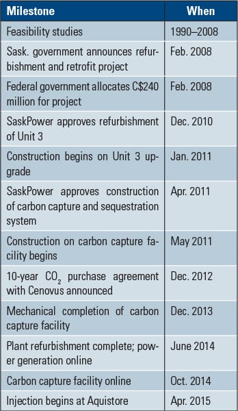 |
| Table 1. From commitment to completion in six years. Source: SaskPower |
When asked why SaskPower chose an amine-based capture technology, Randy Bye, CCS production manager, explained that the company looked at pre- and post-combustion processes and rejected the most costly, eventually choosing the energy penalty of an amine system over less-proven options “on the bleeding edge.” Shell-Cansolv’s post-combustion capture technology was chosen, with SNC-Lavalin as the engineering, procurement, and construction contractor (EPC), as a result of a request for proposals that called for bids from technology-EPC partnerships.
As a result of the CCS retrofit and other Unit 3 upgrades, discussed later, SaskPower is anticipating that Unit 3’s service life has been extended by 30 years.
Projects of this scale and uniqueness don’t come to fruition without dedicated effort from talented people. Vice President of Carbon Capture and Storage Initiatives Ian Yeates explained in emailed comments that one of SaskPower’s strengths is its ability to take on large initiatives in a way that accesses the broad skills of its people. “In the case of BD3, expertise from all areas of the company, starting with the executive and leadership team, but more importantly extending to the individuals who actually get things done, was focused on completing the project successfully…. The success of the project truly belongs to the company as a whole.”
Delivering a First-of-a-Kind Project
The province got serious about developing the BD3 project in February 2008, which was also when the Canadian federal government allocated C$240 million for it. Construction on the boiler island upgrade began in January 2013; construction on the CC retrofit project officially began in May 2011.
Though the BDPS site isn’t as space-constrained as some, Dalton Giblett, the site’s non-building facilities manager, noted that while construction was under way on Unit 3 and CC projects—as well as other capital projects—it was impossible to get from one side of the plant site to the other without making a long detour. There were 250 to 275 workers on site prior to the project and nearly 1,500 during project construction. Just managing the safe movement of all those extra people was a challenge.
Most large power projects these days involve a global supply chain, but this project is arguably more international than most—from the suppliers of turbine (Figure 2) and heat exchangers to the sequestration site monitors. Many of the primary partners and vendors are listed in Table 2.
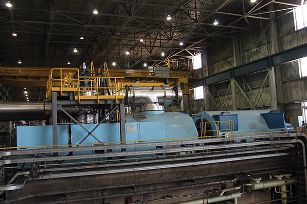 |
| 2. New prime mover. A new 160-MW turbine from Hitachi was essential to giving Unit 3 a new lease on life. Source: POWER/Gail Reitenbach |
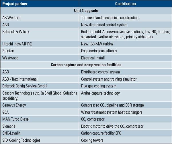 |
| Table 2. Primary project vendors and partners. Source: SaskPower |
Schedule and Safety
Although the capture plant was approved in May 2011, widespread area flooding soon thereafter, plus a missed opportunity to close in facilities before winter, pushed out that plant’s online date. The unavailability of tradesmen (who were in high demand at the time in western Canada’s oil and gas industry) also pushed the schedule in the wrong direction for awhile. Nevertheless, the project reached completion much faster than similar projects still in progress or canceled.
Bruce added after the tour, “A great source of pride for our construction and safety staff is that there were no lost-time injuries during the construction of either the capture plant or the power plant. This is an incredible achievement given the scope of work and the 4.5 million manhours of construction that were completed.”
Capturing Carbon and Sulfur
The carbon capture part of the operation begins at Unit 3. After passing through an electrostatic precipitator, the flue gas is diverted from the stack to a duct that runs between the power building and the capture building (Figure 3).
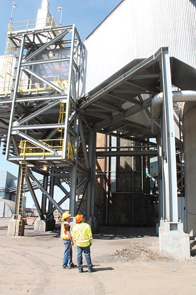 |
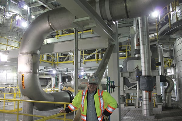
| 3. Diverted flue gas. Scott Walton, production manager for Units 3 and 4, and Corwyn Bruce, manager of carbon capture and sequestration initiatives, look up at the point where the flue gas ducting leaves Unit 3, headed to the capture facility. Steam and its returning condensate, as well as a small capture facility wastewater stream and a few other services, are suspended on the same structure that holds the ducting. Source: POWER/Gail Reitenbach |
Though it’s called a carbon capture plant, the system used at BD3 also captures SO2; in fact, SO2 is stripped first (a process that is more common), and then the remaining gas is sent to the CO2 stripping process (Figures 4 to 6), which uses “the real designer amine in this process,” as Bye described it. The two different proprietary amine solutions are both recycled onsite. A separate closed-cycle water treatment system and cooling towers were built for the capture facility to ensure that if any amine ever leaked, it would not be released to the environment.
 |
| 4. Three-step process. After being piped from Unit 3, flue gas runs through the SO2 absorber (the shorter tower on the left), then through the CO2 absorber (the taller tower with water vapor showing), and then the CO2 is released from the amine in a stripper before being sent to the adjacent compression facility. Source: POWER/Gail Reitenbach |
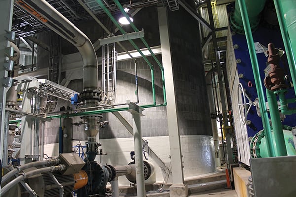 |
| 5. CO2 lean amine tank. To prevent degradation of the concrete absorber tower, 70,000 ceramic tiles line the inside. Similar construction was used for the amine tank. Source: POWER/Gail Reitenbach |
 |
| 6. Looping CO2. Dave Jobe, director, carbon capture operations, is responsible for operation of the carbon capture and compression facilities and is shown here in the capture plant where CO2 leaves the CO2 reflux accumulator, the last chemical stage before compression. Source: POWER/Gail Reitenbach |
After work on the acid plant inside the CC facility is finished this summer, the stripped SO2 will be converted into commercial sulfuric acid. Roughly a tank and a half per day can be converted for use in fertilizer, filtration systems, chemistry labs, or a wide variety of other industrial purposes.
The post-combustion amine-based CC equipment is designed to capture up to 90% of CO2 from Unit 3 using the Shell Global Cansolv technology. (For an overview of currently available CC technologies, see “CCS Development, the Key to Coal Power’s Future, Is Slow” in the May 2015 issue.) Given the proprietary nature of the technology and amines (see http://bit.ly/1J618uy), no photos of that part of the facility were allowed.
The solution with CO2 is sent to the CO2 stripper, where the CO2 is released from the amine in a gaseous form. It’s then pressurized in an adjacent building (Figure 7) to 2,500 psi, to a supercritical state—a process that accounts for the largest share of the parasitic load. At that point, it is sent via pipeline to the metering station (Figure 8), where the feed is split for disposition at an enhanced oil recovery (EOR) field 41 miles from the plant or a geological injection site 1.2 miles away.
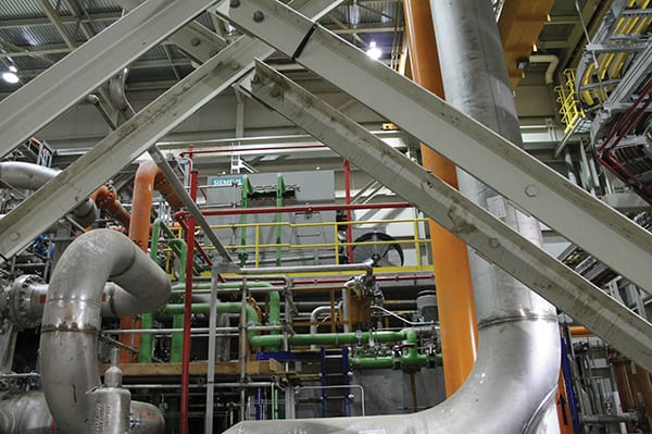 |
| 7. A complex network. Both the carbon (and sulfur) capture building and the compression building, shown here, are multilevel facilities with a dizzying array of piping. The Siemens synchronous electric motor drives the CO2 compressor. Source: POWER/Gail Reitenbach |
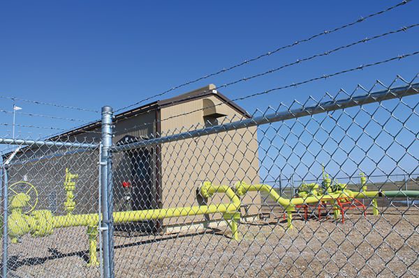 |
| 8. Metering station. Compressed CO2 is piped underground from the compression building to the Cenovus Energy metering station, 3 miles away. The gas flow is metered and split inside the building shown here. Cenovus sends a portion down one pipeline to its fields for enhanced oil recovery and a portion is sent via pipeline in a different direction to the Aquistore geologic injection site. Source: POWER/Gail Reitenbach |
Those unfamiliar with carbon capture (and that’s most people), might wonder how plant operators can tell how much CO2 is being captured and stored. The short answer is, by reading the meter at the point where CO2 is sent underground from the compression building (Figure 9).
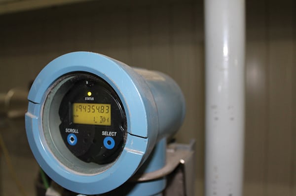 |
| 9. Gas meter. This gauge shows operators the pressure, volume, and flow of compressed CO2 leaving the compression facility via pipeline. Source: POWER/Gail Reitenbach |
Storing Carbon
Critics have argued that although 90% of the flue gas CO2 can be captured, much less will actually be stored—whichever method is used. On the contrary, says SaskPower, CO2 from BD3 will stay underground whether used for EOR or put into permanent storage once the capture plant is fine-tuned later this year and is operating at 100% rather than 90%.
Storage via EOR. Saskatchewan has a long history of oil and gas development and, like many other areas, it has adopted EOR using compressed CO2 to maximize the yield from developed plays. Prior to the BD3 project coming online, Alberta-based Cenovus Energy, which operates the nearby Weyburn Oil Field, could only purchase CO2 from North Dakota. As of May, Cenovus was taking 1,780 mt per day from BD3.
Obviously, maximizing the amount of gas sold for EOR improves the economics for any CCS project.
Storage via Geological Sequestration. Compressed CO2 not sold to Cenovus is sent to the Aquistore site, which came online in April. SaskPower’s Carbon Storage and Research Centre hosts Aquistore, an independent research and monitoring project administered by the Petroleum Technology Research Centre (PTRC). Aquistore is responsible for managing non-EOR CO2 monitoring and storage.
At Aquistore, the CO2 is injected 3.4 kilometers (2.1 miles) deep into a layer of brine-filled sandstone called the Deadwood Formation. SaskPower explains that this formation is at the bottom of the enormous Williston Basin, “a sedimentary basin that is made up of many layers of porous and non-porous rocks.” The Williston Basin reaches far into the U.S., Saskatchewan, and Manitoba and has the potential to store all CO2 captured at Boundary Dam.
Aquistore’s injection well was designed for the injection of up to 2,000 mt per day (roughly half of the total captured by Unit 3) for scientific research and secure, permanent storage.
Kyle Worth, PTRC senior project manager, explained that the dozens of monitoring stations managed by PTRC allow researchers and the project team to understand how injection is proceeding and where the CO2 is settling in the reservoir. Although any leak of CO2 is unlikely, the monitoring technologies deployed will notify the project should anything unexpected occur so immediate action can be taken. Worth said Aquistore monitoring is built on decades of experience and the site is the best-equipped for CO2 monitoring in the world. The surface monitoring installations shown in Figure 10 provide assurance by way of soil-gas, groundwater, and surface deformation monitoring. Three years of baseline surveys were conducted to establish the natural state of the environment prior to CO2 injection.
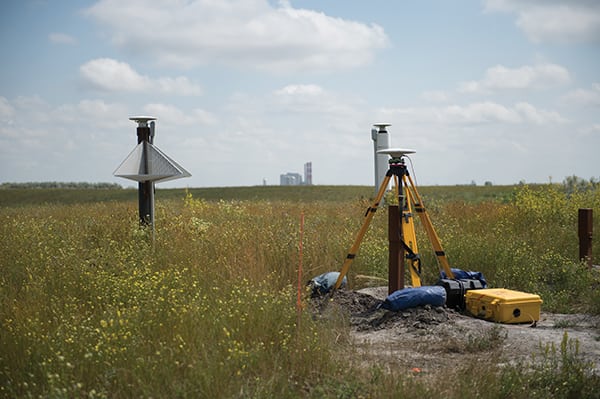 |
| 10. Monitoring buried CO2. Boundary Dam Power Station is visible behind one of Aquistore’s co-located monitoring “super-stations,” which include drilled water-monitoring wells, soil-gas sampling ports, a weather station, a broadband seismometer, plus inSAR, GPS, and tiltmeters (which measure surface uplift and changes). Courtesy: Aquistore |
Below the surface, Aquistore has other monitoring equipment, including underground pressure and temperature gauges, fluid sampling ports, and fiber-optic lines, which can help visualize the CO2 in the subsurface. Aquistore’s injection well and observation well are also monitored using additional gauges and an extensive well-logging program. The observation well is a “smart well” that is heavily equipped with state-of-the-art monitoring equipment to allow experts to track and visualize CO2 in the reservoir 3.4 km below the surface.
Upgrading the Power Station
Although the carbon capture facility has received the lion’s share of media attention to date—for good reason—Unit 3 upgrades made in conjunction with the capture plant construction also deserve attention. As you might expect, a nearly 50-year-old unit required a few updates in order to appropriately support a sophisticated CC system. Major aspects of the Unit 3 retrofit project included the following:
■ The boiler was upgraded, with all convective surfaces being replaced and increased in size, including superheater, reheater, economizer, and air heaters. A separated overfire air system and low-NOx burners were added.
■ A new Hitachi turbine and generator, capable of supporting the large steam extraction required for the CC plant, replaced the existing turbine.
■ The main steam line was replaced, and steam piping was modified to support a 50 degree F steam temperature increase.
■ The feedheating plant required total replacement to deal with the varying demands from the capture plant and allow the plant to operate at full output when it is and isn’t in CC mode.
■ The condensate system was heavily modified from a traditional design to allow thermal integration with low-grade heat available from the capture process.
■ Diverter dampers were added to the stack to allow flue gas to be sent to the capture plant.
■ A new control system was installed, and arc flash–resistant switchgear was installed.
Creating Synergies. Integration of the power and capture plants was the key to minimizing the parasitic load associated with the CC process. For example, Bruce explained, sourcing of the steam—which is required to release gases from the amines—from an uncontrolled low-pressure turbine extraction (after the steam has already done most of the useful work it can in producing electricity), and returning the resulting condensate to the power plant’s deaerator, greatly reduced parasitic load.
Other synergies start at the capture plant. For example, the CC process requires the flue gas to be cooled significantly, so an acid-resistant heat-recovery system—the flue gas cooler—captures heat, which is then used to replace the condensate heating duty of the entire low-pressure feedwater system for Unit 3 (Figure 11).
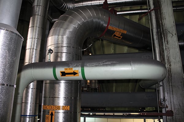 |
| 11. Steam synergy. In a unique sort of combined heat and power scheme, extraction steam from the turbine is sent to the carbon capture building to supply the reboilers, an integral part of the carbon capture process. Source: POWER/Gail Reitenbach |
Even though amines from the sulfur and CC processes are recycled in a closed system onsite and the capture facility has a closed-cycle cooling system, a small waste stream needed to be dealt with. When engineering determined that the water treatment for this waste stream was not able to deal with all of the contaminants, an interim plan was devised to pipe that small amine-bearing wastewater stream back to the power plant and incinerate it safely in any or all of three boilers (Figure 12).
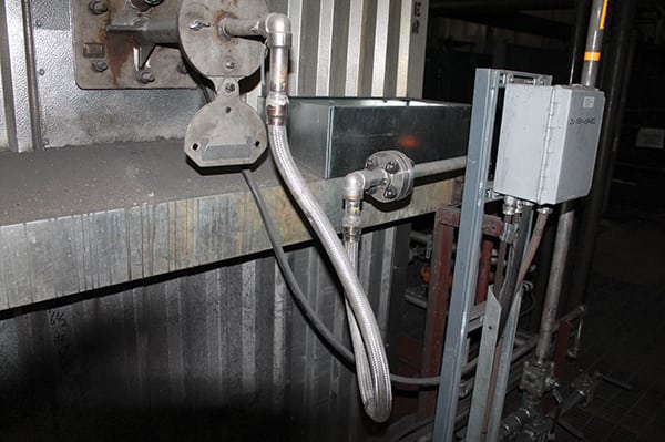 |
| 12. Waste incineration. A small wastewater stream from the carbon capture facility is sent to the boilers for safe disposal via combustion. Source: POWER/Gail Reitenbach |
Based on the life of the existing equipment, and the opportunities to take advantage of efficiency improvements that have become mainstream since the plant was originally built, extensive work was undertaken to integrate all improvements that could be made cost-effectively. A dedicated heat integration engineer focused on delivery of an integrated design that maximized unit output based on capital construction and operating costs. Heat integration studies required many iterations between the owner’s engineer (Stantec) and technical experts from Hitachi, Babcock & Wilcox, and Babcock Borsig Service to achieve the final solution.
With a unit gross output increase from 150 MW to 161 MW in noncapture mode and full net output in capture mode (including all design margins) that is very conservatively pegged at 110 MW (early performance results indicate that final net output performance should be around 120 MW), the results far exceed the expectations at the project’s inception, Bruce said.
Emissions Control. Aside from the CO2 and SO2, which are captured in the new facility, other traditional emissions from Unit 3 are managed both according to regulation and capture process needs.
NOx, which is not regulated in Saskatchewan, is controlled with overfire and underfire air and low-NOx burners, which has dropped emissions 50%. NOx “is not a friend of amine-based systems,” Bruce noted.
Mercury is not controlled at BDPS, although activated carbon injection is used at the nearby SaskPower Shand and Poplar River stations.
As for particulate matter from Unit 3, the flue gas is washed at least seven times after the precipitator, so it’s at virtually zero after the capture process, Bye noted.
Staffing and Control
Initially, SaskPower intended that the CC facility would be unmanned and controlled from Unit 3’s control room. As the project progressed and the CC water treatment plant was added, however, plant managers decided it would be better to staff the CC system like a power plant, with three to four operators and a shift supervisor. The idea was to cross-train the CC and Unit 3 control room staff. However, that plan was further revised. The CC plant has five shifts in rotation with six personnel per shift: a shift supervisor, two process operators in the control room, one water treatment plant operator, and two facility operators on the floor.
Bye noted that each operator had at least 40 hours of simulator training before the CC facility came online. Trax International (a subcontractor of ABB) provided the digital simulator as part of the control system (Figure 13), though a senior operator who was very involved in the factory acceptance test in Lynchburg, Va., conducted the actual training.
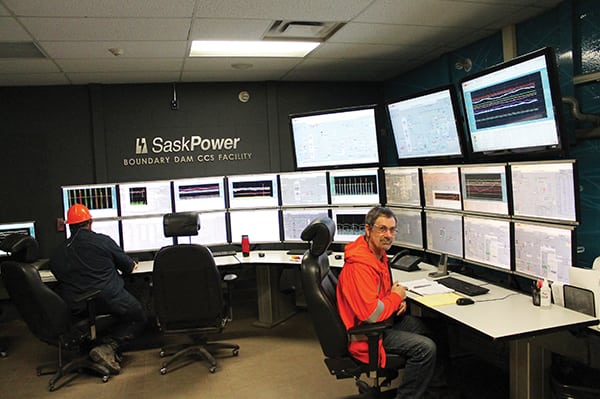 |
| 13. Controlling carbon capture. Loyd Leblanc (foreground) and Ron Wonch are shown in the control room of the carbon capture facility, which looks much like the new Unit 3 control room. Source: POWER/Gail Reitenbach |
SNC-Lavalin had suggested hiring process or chemical engineers, as they have been used at previous Cansolv gas sweetening plants, but SaskPower went with power engineers (in part because it was considering cross-training between power and capture plant operators). Those power engineers received about 400 hours per person of specialized classroom training on process chemistry and the processes involved at the BD3 plant. Bye said, “I still believe that power engineers are the best qualified to run the [capture] plant.”
Though Units 3 and 4 share a control room, they do not share control stations. Unit 4 continues to use its original equipment, while Unit 3 got a complete digital upgrade (Figure 14).
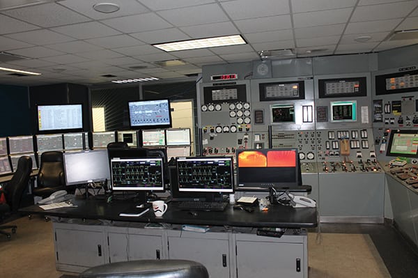 |
| 14. Old and new power controls. On the right are the original controls for Unit 4. On the left is a portion of the upgraded, digital control system for Unit 3. Source: POWER/Gail Reitenbach |
The plant’s maintenance staff, rather than the EPC, did the commissioning work, which gave everyone from mechanics and electricians to instrument techs hands-on initial troubleshooting experience.
Unit 3 can operate if the capture facility trips offline for any reason, ensuring continued, reliable power delivery. The only thing that happens at the power island is that the diverter damper quickly changes position to send flue gas up the unit’s stack instead of over to the capture building. That happens in under a minute, Walton said.
First-of-a-Kind Hits and Misses
Although amine-based sulfur and carbon capture have been done before BD3, this is the first time the process has been deployed at scale on an operating power plant, where power generation remains the primary business goal. In order to mitigate anticipated unknowns, the plant and SNC-Lavalin built in redundancies and margins for criticial components to ensure smooth operation.
However, even the most prudently planned new project is likely to encounter the unexpected. At BD3, some surprises were equipment related, such as electrical work that had to be redone, valves that leaked before they should have shown wear, and issues with the water treatment plant (which didn’t prevent the capture plant from operating). Unanticipated process changes included adjusting steam flow and temperature control from Unit 3, which had ripple effects on the CC plant. And then, Walton noted, there were the large icicles that formed on the outside of the CC building as a result of condensation moisture during the severely cold Saskatchewan winter. That problem has been remedied with the use of lots of heat tracing, Bye said. For any future capture plants, staff would insist on putting even more of the capture equipment inside the building to mitigate weather-related nuisances.
Other issues were chemistry related. The waste incineration system mentioned earlier worked, except that it increased boiler slagging, Walton explained. Adjusting the stream’s pH before introducing it to the boiler has helped to mitigate that problem.
Other systems, like the flue gas cooler system (which must be operating for the capture facility to run), have operated flawlessly since startup, Bye said. That system, provided by Babcock Borsig Service, GmbH out of Germany, had to work, he said, as no redundancy was built in. The project planning team went to Germany, Italy, and Thailand to look at operating flue gas coolers to ensure they chose the right one for their needs. The CO2 compressor, from MAN Turbo Diesel, also has been really good, said Bye, “It just purrs.”
Now that SaskPower has some operating experience with all the parts working together, staff have discovered a few places where redundancies could be reduced for future units, thereby saving both capital cost and energy penalties.
Early Performance
When the staff I met with talked about the first CO2 capture in September, they still exuded excitement. That first, successful attempt to capture the gas—which happened at 1 a.m., with a control room packed with onlookers—went so smoothly that they still seem surprised. The first sale of CO2 occurred October 1.
On February 11, SaskPower issued a press release concerning preliminary performance data from BD3. Mike Monea, SaskPower’s president of carbon capture and storage initiatives, was quoted as saying, “The project is generating vast amounts of data never before available to scientists and engineers around the world, and the numbers are very impressive.”
Approximately 135,000 mt of CO2 had been captured between the project’s official launch and February. CO2 purity was virtually 100% (4.5% better than expected), while the parasitic load was 10 MW lower than expected.
The capture plant went offline about 10 times during the first six months, largely due to chemistry issues and problems like demisters plugging. However, the process itself is fairly reliable thanks in part to the built-in redundancies. A year from now, Bye said he expects the capture facility to “run the same amount of time that Unit 3 does.” Plantwide performance data (as of May 2015) are shown in Table 3.
 |
| Table 3. Boundary Dam Unit 3 carbon capture project performance. Source: SaskPower |
Economics
There’s no sugar-coating the fact that current options for CCS at fossil-fired power plants are expensive as well as technically challenging. BD3’s CCS project cost, according to a February release by SaskPower, is C$1.467 billion. After the Canadian federal government’s C$240 million in subsidies, SaskPower and its customers are responsible for the balance. Cost overruns totaled more than C$200 million. SaskPower notes that this first-of-its-kind carbon capture plant was finished on budget; challenges associated with the existing power plant were the cause of cost overruns.
In contrast to the BD3 project, the two major pre-combustion CC projects in the U.S. have seen significant cost overruns. Duke Energy’s 618-MW Edwardsport integrated gasification combined cycle (IGCC) plant in Indiana was two years behind schedule, US$1.5 billion over budget, and continues to experience mechanical troubles that prevent it from operating at 100% capacity. Mississippi Power’s 582-MW Kemper County IGCC project, also behind schedule, is now projected to cost over US$6 billion—nearly triple its initial projected cost of $2.2 billion. In May, the Kemper project lost a key power buyer because of the delays and cost overruns. Meanwhile, NRG Energy Inc.’s 240-MW post-combustion CC project in Texas, at the WA Parish plant (also designed to support EOR), broke ground in September last year. That project, with an estimated cost of US$1 billion, is scheduled for completion in 2016 and designed to capture 90% of CO2 emissions.
As a government-owned utility, SaskPower has a bit more flexibility in backing a financially challenged first-of-a-kind project than the typical investor-owned or merchant generator. Yeates observed that, “One essential component of this is the interest rates we pay given the province’s AAA credit rating. No commercial corporation can touch that, and it saves bundles.” Several observers have noted that the project’s ability to support the province’s coal and oil resources are also major elements of its anticipated long-term success.
SaskPower retail rates, like those of other utilities, vary by customer class. Residential energy rates for 2015 range from 12.346¢/kWh to 12.369¢/kWh. (For comparison, average residential rates in the contiguous 48 states range from 8.65¢/kWh to 21.82¢/kWh.) Though SaskPower asked for a 15.5% rate increase over three years in 2013, the government approved an initial 5.5% increase for 2014 but lowered the 2015 increase to 3%. Bill Boyd, the provincial minister responsible for SaskPower, would not say that the BD3 project was responsible for the increase and pointed instead to the utility’s 10% demand growth over the past two years as a reason for the rate hike, according to an April 14 story in the capital’s newspaper, The Regina Leader-Post.
Groups favoring more renewables have argued that SaskPower should instead have developed more wind power in the province, though an equivalent amount of wind power would require some dispatchable firming capacity and would certainly have resulted in rate increases as well. Renewable sources currently make up about 25% of Saskatchewan’s power, and SaskPower says it is working to add more.
Though the relative economics of different fuel portfolios will vary geographically—as determined by resources, markets, subsidies, and regulatory requirements—there’s no denying that CCS carries both capital and operational cost premiums, both in terms of added operational and maintenance expenses and lost power sales. That’s likely one reason that the only post-combustion capture projects to make headway have involved byproduct sales.
As noted earlier, both the captured CO2, when used for EOR, and SO2, used in a variety of processes, can create revenue streams. SaskPower says that fly ash will also be sold “for use in ready-mix concrete, pre-cast structures and concrete products.” For the project’s first 10 years, CO2 for EOR is contracted to Cenovus Energy at a cost of about $25/mt (the actual cost has never been disclosed). Annual revenue from CO2 is estimated to be up to $25 million.
SaskPower says that, based on the knowledge gained from BD3, preliminary estimates suggest that it could save up to 30% on its next CC project. In April, Monea told the Financial Times that the company will make a decision by late 2016 or early 2017 about building two more CCS facilities (at Units 4 and 5).
Even with some sort of carbon pricing scheme, CCS may prove challenging for plants without easy access to appropriate injection sites. BD3 has what is clearly an ideal set of circumstances.
An Industry Leader Breaking Boundaries
In order to reach environmental goals of a lower-carbon future while ensuring access to affordable and reliable electricity for people around the world, we need proven, effective, affordable options that can be widely deployed. Although the type of CCS technology deployed at BD3 may not be suitable for all fossil power plants, it is likely to be one of the viable first-generation options.
SaskPower is continuing to advance CCS technology with its Shand Carbon Capture Test Facility (CCTF) at the Shand Power Station, also near Estevan. This facility, developed in collaboration with Mitsubishi Hitachi Power Systems, started operating on June 18, 2015, and is designed to provide a proving ground of sorts for a variety of amine-based, post-combustion technologies. SaskPower explains that, “It has the capacity to add and remove process equipment, change the configuration of vessel internals, and expand the height of the key absorber vessel.” In SaskPower’s employee magazine, Monea notes that, whereas BD3 is rated at 3,200 mt CO2/day, the Shand test facility will handle 120 mt/day—roughly 2% of Shand’s flue gas. “The (CCTF) facility will be one of the largest in the world,” he said.
In addition to two onsite chemistry labs at BD3 (Figure 15), the company is also supporting the broader CCS project with an Amine Laboratory in Regina. Its role is analyzing environmental and occupational health and safety samples from the CCS facilities for environmental contaminants that may be produced as a result of carbon capture. The goal is environmental safety. (Concerns about possible amine-based health risks stalled work on Norway’s Mongstad refinery CCS project in late 2010.) SaskPower’s international collaborators in the Amine Laboratory work include TNO from the Netherlands, TCM Mongstad in Norway, and the U.S. National Carbon Capture Center.
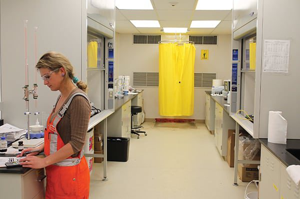 |
| 15. Unique job. Khrystyna Vasylkiv, plant chemical technologist, works in one of two chemistry laboratories at the carbon capture plant, where she and her colleagues are engaged in a new type of power plant job. Source: POWER/Gail Reitenbach |
SaskPower’s CCS Global Consortium is open to “businesses, governments, research groups, educational institutions, and stakeholder organizations interested in advancing CCS in their jurisdictions.” Global cooperation is important because, as Gassnova’s chairman of the board, Einar Steensnaes, said in a video interview, CCS is “important, but we have learned that it is not so easy to realise those projects.”
Representatives from more than 30 countries have visited BD3, and Monea was quoted in the Financial Times article as saying that a Chinese delegation visits BD3 “every two or three weeks.” He continued, “China is just gathering information right now. When it moves, it will be significant. I think that’s where the next projects of size and number will be happening.” (Readers can take a virtual tour of the plant and carbon capture facility by visiting http:// saskpowerccs.com/tour/.)
What’s especially notable about the BD3 project is that, beyond simply integrating CCS into a single unit, SaskPower has developed a larger supporting ecosystem for ongoing research, monitoring, and project development. As a government-backed utility, SaskPower does have advantages that some of its peers around the world may lack. However, it says something about both SaskPower and the province of Saskatchewan that a geographically large (251,700 square miles) but sparsely populated region (1.13 million) and small utility (serving roughly half a million customers) reached the finish line first—and with fewer technical, budgetary, and political setbacks than might have been expected.
People at the Heart of the Plant
Nobody who interacts with the BDPS team could fail to see their well-justified pride in what they have accomplished. But their achievement took serious stretch efforts over the long term. Walton made sure to note the dedication of SaskPower’s employees from across the company, who sacrificed to make the project a success: “They did an excellent job.” Then there was the plant operations and maintenance staff, who “stepped up and worked long hours for a year and four months,” Walton noted. “Everyone invested a lot to make this succeed.”
The regulation of CO2 emissions is a sensitive topic in some corners of the power world, and I’m sure there are those even within the SaskPower orbit who still do not support such regulations. Nevertheless, those I spoke with noted that staff looked at this project as an opportunity. As Dave Jobe said, if coal power is to have a future, this is it. ■
— Gail Reitenbach, PhD is POWER’s editor.