Morris Cogeneration, a combined cycle cogeneration plant near Chicago, has installed TurboPHASE, a fast-responding, modular “turbocharger” installed to boost capacity and PJM regulation revenue. How does it perform?
Twice this year, PJM flirted with blackouts when brutal winter storms (dubbed a polar vortex) struck the Eastern U.S. in January. The cold weather set a new winter peak demand record of 141,500 MW on Jan. 7, busting the record set in February 2007 by nearly 5,000 MW. In fact, the five biggest demands ever placed on the PJM grid, and eight of the 10 largest, occurred between Jan. 7 and Jan. 30. PJM reported that at one point, 36,000 MW was out of service due to forced outages, which amounts to 20% of its installed capacity. Adam Keech, director of wholesale market operations, is reported by RTO Insider as saying—the morning after setting the winter peak record—“We really exhausted every megawatt we had on the system.” Peaking capacity and fast unit response is a necessity during summer and winter peaks, and many regional transmission organizations (RTOs) are willing to pay well for the service.
A solid majority of new plant construction in PJM is gas fired, led by simple or combined cycle plants. Simple cycle combustion turbine (CT) plants are less efficient than combined cycle plants but are able to start more rapidly and add valuable power to the grid in minutes, which is extremely valuable to a system like PJM as synchronized reserve, fast grid regulation, or black start service. In fact, ancillary service payments often justify the cost of constructing a simple cycle peaking plant.
A New Option
Jupiter, Florida–based PowerPhase LLC has successfully demonstrated a new technology called TurboPHASE that may allow an existing simple cycle CT or combined cycle plant to add as much as 10% to 20% more power to the grid in seconds, depending on plant configuration, addressing the quick-start and fast-response needs of the modern grid.
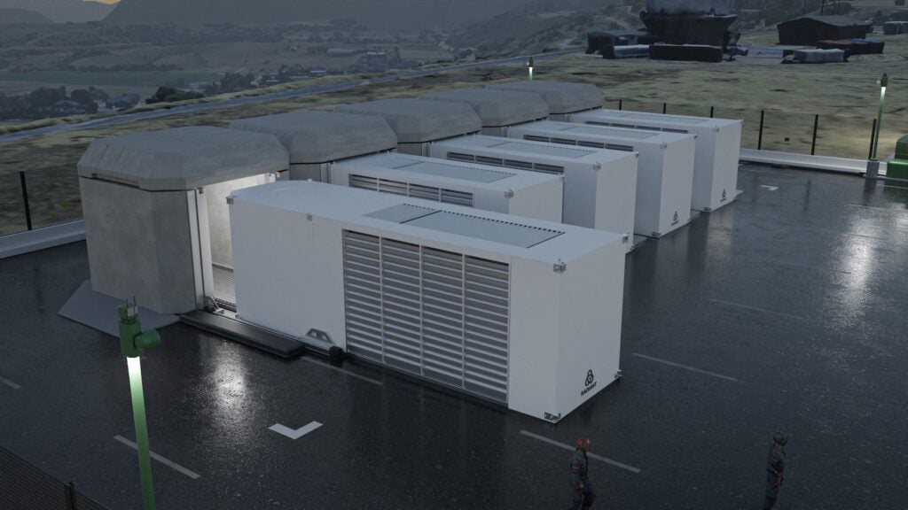
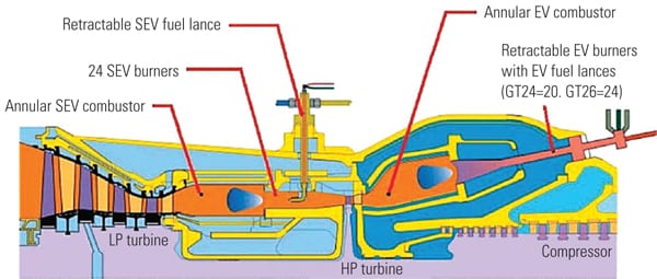
The TurboPHASE system consists of a multistage intercooled centrifugal compressor that delivers hot compressed air to the CT’s compressor discharge section, thereby allowing the CT to operate at its rated capacity irrespective of the ambient conditions (5C to 50C) or altitude (Figure 1). The system takes advantage of the CT operating below its limits during hot weather much like an inlet chiller or evaporative cooling system, although TurboPHASE can also operate in conjunction with either of those inlet cooling options.
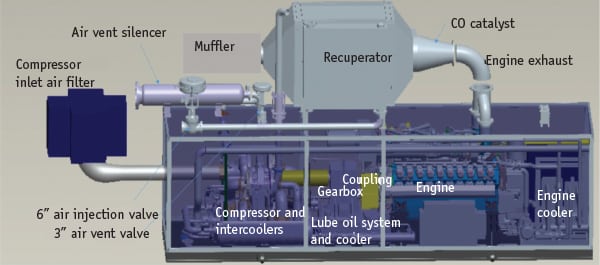 |
| 1. Turbocharging combustion turbines. TurboPHASE consists of four main components: engine, gearbox, compressor, and recuperator. A gas-fired engine-compressor set produces compressed air that is added to the combustion turbine’s compressor discharge section to negate the effect of a high ambient temperature performance derate. Courtesy: PowerPhase LLC |
A separately fueled reciprocating engine direct drives the compressor. The heat from the exhaust of the engine is used to heat the compressed air in the recuperator before entering the CT compressor section. On an operating CT, TurboPHASE is said to be able to ramp to full load in 60 seconds or less and from part load to full load in 10 seconds or less. This design feature is sure to be of interest to grid dispatchers anxious to have the ability to quickly backfill lost capacity during a system emergency or to quickly respond to the intermittency of renewable resources.
Field Tests Completed
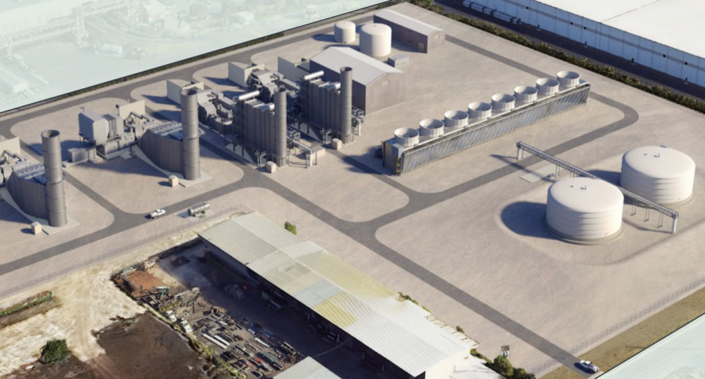
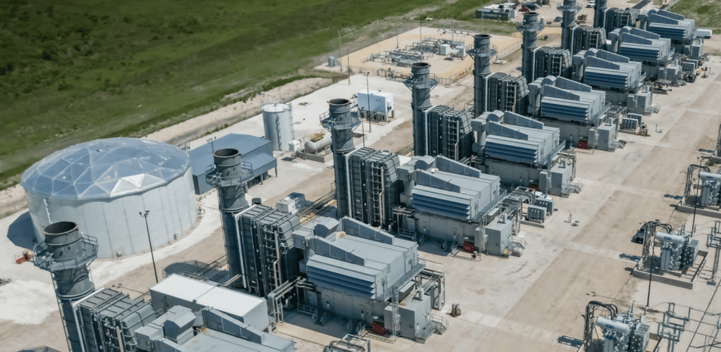
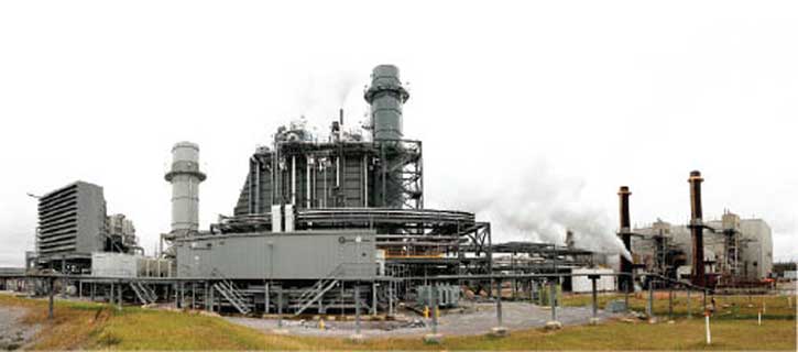
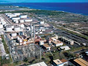
Two prototype TurboPHASE modules (TPMs) were tested in August, and the data and test results were provided to POWER on an exclusive basis. The tests were conducted at Atlantic Power Corp.’s Morris Cogeneration Plant (Morris), located just outside Chicago (Figure 2). The gas-fired 177-MW combined cycle facility is located within the Equistar Chemicals petrochemical plant in Morris, Ill. All of the steam (after passing through a steam turbine) and a portion of the electricity produced by the plant is sold to Equistar, and the remainder of the power is sold into the PJM West market. Morris is configured with three gas-fired General Electric Frame 6B CTs, each with a heat-recovery steam generator (HRSG).
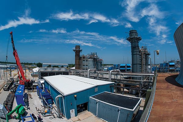 |
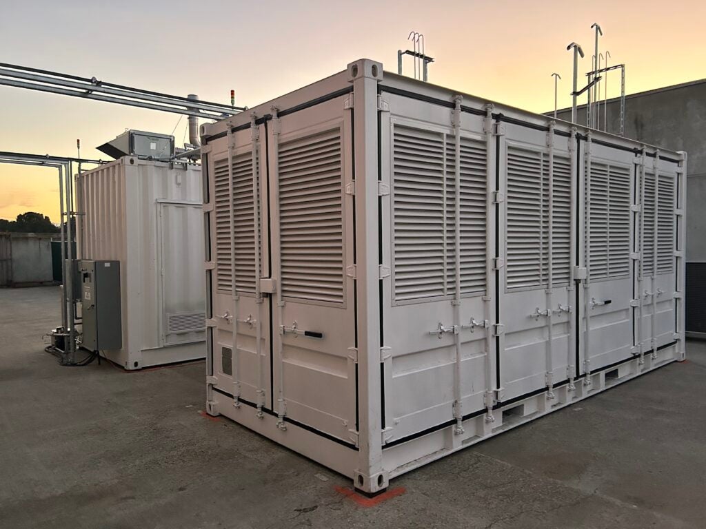
| 2. Demonstration plant. Two TurboPHASE modules (TPMs) were installed at Atlantic Power Corp.’s Morris Cogeneration Plant (lower left of photo) and were recently performance tested. The TPMs each added over 3 MW of quick response capacity to a Frame 6B combustion turbine and steam turbine system. Courtesy: PowerPhase LLC |
PowerPhase engineers ran a series of predictive performance models using ThermoFlow in advance of the field tests. The models predicted that the CT full-load performance would increase ~2.63 MW and the steam turbine by ~0.43 MW, for a total power increase of ~3.06 MW. The cost of the increased output is the additional fuel burned by the CT (~10 MMBtu/hr) and the fuel burned by the engine (~16.3 MMBtu/hr). Therefore, the incremental heat rate of the unit with one TPM in service was expected to be on the order of 26.3 MMBtu/hr/3.06 MW = 8,650 Btu/kWh.
The demonstration test was conducted in two parts. The first test was designed to demonstrate the increase in output capacity when using a single TPM. The second test measured the response or ramping speed of the plant with one or two TPMs injecting air into the plant’s CT1. Each of the TPMs used at Morris is powered by MTU 20V4000L32 gas-fired engines, each rated at 2 MW.
Morris is also equipped with inlet chilling and HRSG duct-firing capability, and both were in operation during the demonstration tests. The tests were conducted with the CT at full power at an ambient temperature that averaged ~85F. At no time during the tests were the operating limits of the CT exceeded.
Day One Tests. On the first day of testing, compressed air from TPM2 was injected into CT1 as the system cycled off and on three times. Data was collected at one-second intervals and then averaged. CT fuel flow measurements were taken from plant instruments, and TPM fuel flow was measured (at the inlet to the engine) at 16.3 MMBtu/hr as expected. TPM air injection flow rate was measured by an annubar-type flow meter on the main air header prior to entering the CT. The airflow from each TPM was measured as 11.5 lb/sec at ~156 psi.
The measured test results at Morris showed that the average CT power boost was 2.74 MW and that the steam turbine produced an additional 0.32 MW, for a total power increase of 3.06 MW per TPM, very close to the prediction. As an additional benefit, the TPM compressor intercoolers produced an average of 1.2 gallons per minute of clean water during the tests.
The second test of the day was measurement of the plant response to a demand signal. The test procedure was to first ramp up TPM2 to full speed, no load. No compressed air was produced by TPM2 while the system was idling. When warmed up, TPM2 was ramped up to 75% load while venting the compressed air produced to the atmosphere through a vent valve, bypassing the CT.
Simulating receipt of a demand signal with TPM2 at 75% load, the vent valve was closed and the injection valve was opened, thereby sending compressed air to the CT compressor discharge. The air injection quickly produced an incremental power increase of about 1.5 MW, ramping up to ~2 MW when the vent valve was fully closed and injection valve was fully open. Next, TPM2 was ramped to full power, and the CT responded by producing an increase of ~2.74 MW, with the steam plant power increase following. The test ended with the load on TPM2 reduced to 75%, followed by opening the vent valve and closing the air inject valve to the CT. Figure 3 shows the results of the response testing completed on day one. The TPM was able to add much, although not all, of the incremental power from the CT within the 60-second goal set by the company.
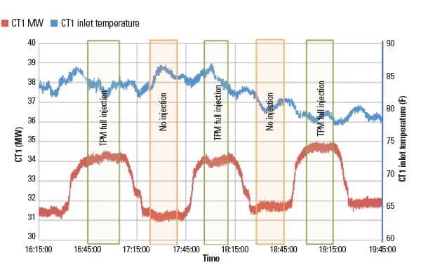 |
| 3. Day one tests. Results of the first day of TurboPHASE demonstration tests are illustrated. The blue line represents the temperature at the inlet to the combustion turbine. The orange line shows the response of the combined cycle plant to full air injection. Courtesy: PowerPhase LLC |
Day Two Tests. The response tests were repeated on the second day of testing using TPM1. Figure 4 illustrates the data collected during these tests, which were very consistent with the previous day’s tests.
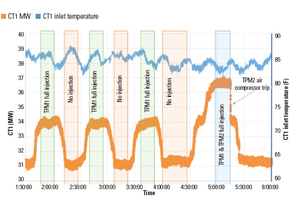 |
| 4. Day two tests. The test results of the second day of TurboPHASE demonstration tests are illustrated. The last test of the day was with both TurboPHASE systems in operation followed by a trip of one system. Courtesy: PowerPhase LLC |
The second test of the day was to run both TPMs in parallel and inject the produced compressed air into CT1. The final test simulated an unexpected trip of a TPM. When the air supply from TPM2 ceased, a check valve in the TPM prevented reverse flow, and TPM1 continued supplying compressed air to the CT as expected.
The piping system pressure drop between the TPMs and the CT was ~11 psi with one TPM operating (flowing 11.5 lb/sec) rising to ~40 psi with two TPMs operating, so the airflow into the CT was slightly less than double (22 lb/sec). The pressure drop effect is apparent in Figure 4 where a single TPM produces ~3 MW while two TPMs produce slightly under ~6 MW. A line size increase from 6 inches to 8 inches would solve this problem, but since Morris doesn’t anticipate operating the plant in this manner, the cost of the pipe size increase isn’t justified.
Pluses and Minuses
Before assessing the results of the testing, it’s best to remember that this was the first full-scale demonstration test of the TurboPHASE and we were privy to only an overview of the testing and the performance results. That said, we are still able to reflect on the performance of the system in relation to the important ancillary services PJM and other RTOs desire: synchronized reserve, fast grid regulation, and black start service.
Synchronized Reserve. A single TPM consists of a single MTU gas-fired engine that will produce 2 MW were it fitted with a generator and operated standalone, which is the obvious competitor to the TurboPHASE system. Further, according to data on the MTU website, this model gas engine with a generator operates at a heat rate of ~8,000 Btu/kWh, which is a very efficient engine, and more efficient than the CT. This class engine, in “hot start conditions” (usually defined as lubricating oil preheated, engine bearing prelubricated, and cooling water preheated) can be started and synchronized to the grid in ~60 seconds or less and reach full load in ~90 to 180 seconds. The downside is the extra cost of the generator and switchgear.
The 60-second response of the TPM is based on the engine operating at 75% load with compressed air bypassing the CT. A “start” signal puts the compressed air into the CT and increased power is achieved in ~60 seconds in the CT, about 2.75 MW. The capacitance in the HRSG and steam turbine system brings the remaining ~0.25 MW along well after the 60-second goal. Although the data provided did not state the time period, the two figures are suggestive that the time lag is several minutes, as one would expect.
The report suggested that the average incremental heat rate of the TPM (8,650 Btu/kWh predicted) was 8,495 Btu/kWh based on the full ~3 MW power increase. However, the fuel flow data taken from station instruments showed significant variation, so it’s best to consider the incremental heat rate as anecdotal rather than a hard number. Also, for comparison purposes, a more appropriate incremental heat rate should be based on the CT output alone rather than the CT plus steam turbine output because of the several-minute time lag of the steam system.
How does the TurboPHASE stack up against using the same engine in a standby package for synchronized reserve power? Both packages must be running, in standby mode, and synchronized to the grid to qualify. However, the engine-generator can be synchronized, kept at minimum load (lower fuel consumption), and can take on 2 MW of load within ~30 seconds or so. The TPM must also be running but held at 75% load in order to add 2.75 MW to the grid within 60 seconds, but it does so at a higher heat rate than the engine-generator alone. The economics are very CT and site specific.
Fast Grid Regulation. Once the TurboPHASE is operating, then its response to rapid changes in grid demand must be considered. Although the specific data wasn’t available, the TPM response to a step increase in load demand can be estimated from Figures 3 and 4. The data does confirm that TurboPHASE responds quickly, with the nearly vertical lines representing the CT response followed by the slower steam turbine. The data also shows the CT responds in about 2 to 3 minutes, with the additional steam turbine power available within 10 minutes. The standard PJM response requirement for grid regulation power is 10 minutes. Regardless, adding the TPM did improve the grid response of the Morris plant and may allow the plant to move into a grid response category with a higher payment.
The competitive 2-MW gas-fired engine-generator could also be started, synchronized, and at maximum load in less than the 10 minutes standard to supply grid regulation power. But then again, a simple cycle Frame 7FA (227 MW) can start and reach 50% load within 10 minutes and then ramp up at 40 MW/min. Aeroderivative engines start and synchronize even faster.
Black Start Service. The TurboPHASE has the potential to become an interesting black start option for some utilities with combined cycle plants. However, it’s difficult to compete with a diesel engine when the weather gets very cold (see “Prepare Your Gas Plant for Cold Weather Operations” in this issue), particularly when natural gas supplies are limited for power generation at some gas plants. The best black start systems will be an independent system that can supply power to just the critical plant systems needed for restart. On the other hand, a TPM can be installed in two to three months while a new engine-generator will likely take six months or longer.
Final Analysis
TurboPHASE has the potential for reinvigorating existing combined cycle or simple cycle plants with additional peaking capacity, especially during warmer days when the output of the CT is otherwise limited. The response of the TurboPHASE, from the limited information we have reviewed, is on the same order as a gas-fired reciprocating engine. Efficiency leans toward the engine-generator because the combined cycle plant has a higher heat rate. This balance point could easily change should the TPM be installed on a more efficient CT, although there aren’t many that CTs with a heat rate less than 8,000 Btu/kWh (for example, the 60-Hz 7FA is 8,680 Btu/kWh).
On the other hand, the cost of a TPM is likely less than a bank of centrifugal chillers and coils that are often used to increase CT power output during warm weather. Also, since the TPM produces compressed air at 300 psi, the system can be used on any CT with a compressor discharge pressure of 290 psi or less, which includes many E-, F-, and G-class CTs and some aeroderivative engines, assuming there is a suitable open port on the casing at the compressor discharge.
The response of the TurboPHASE does meet the PJM requirements for grid regulation power but only when the unit is running and the compressor is charged and ready to dump compressed air into the CT. A potential owner must consider the economics of balancing the regulation payments from PJM against the cost of the TPM and the added fuel costs. Also, it probably goes without saying that potential adopters must be located within an RTO that has a grid fast regulation payment scheme.
What do the OEMs think about an owner adding compressed air into the engine casing for peaking power or fast regulation purposes? General Electric’s GER-3567H states, “GE [heavy duty] gas turbines are designed to allow up to 5% of the compressor airflow for steam injection to the combustor and compressor discharge.” If superheated steam injection is acceptable to GE, as it has been for over 30 years, then one would expect that compressed air in like mass flow will also be acceptable. Also, it seems to me that injecting clean compressed air upstream of the combustor is certainly preferable to wet compression resulting from the use of evaporative coolers. ■
— Dr. Robert Peltier, PE is POWER’s consulting editor.