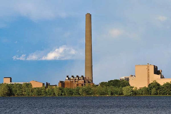
Complying with various state (and expected federal) requirements governing mercury removal from the stack gas of coal-fired power plants has usually been achieved by adding an expensive activated carbon injection system. Now there is another alternative: a catalyst that features higher mercury oxidization activity than conventional catalysts while maintaining the same SO2 to SO3 conversion activity—and all at a lower operating cost. Full-scale installations are under way at several Southern Company plants that burn a variety of coals.
In March 2005, the U.S. Environmental Protection Agency (EPA) announced two final rules for air pollution that apply to coal-fired power plants: the Clean Air Interstate Rule (CAIR) and the Clean Air Mercury Rule (CAMR). CAIR was intended to reduce nitrogen oxides (NOx) and sulfur oxides (SOx) emissions that contribute to high levels of ambient O3 and particulate matter (PM2.5). CAMR separately addressed the reduction of mercury (Hg) emissions from U.S. power plants. Although CAMR was eventually vacated, the release of state rules requiring mercury reduction continued.
These prior federal rules have been replaced by new regulations focused on hazardous pollutants (HAPS), such as the Utility MACT (maximum achievable control technology) Rule proposed in March 2011 and slated to become final in November 2011. In particular, mercury is a major focus of the new regulations, creating new mercury emission control challenges for power generating station owners. In particular, the draft Utility MACT Rule requires that mercury emissions meet a concentration level of 11 lb/TBtu for coal with a heating value less than 8,300 Btu/lb and 1 lb/TBtu for coals with a heating value equal to or greater than 8,300 Btu/lb for existing units. For new units, the targets are a function of generation: 0.040 lb/GWh for coal less than 8,300 Btu/lb and 0.00001 lb/GWh for coals equal to or greater than 8,300 Btu/lb—about one-thousandth the levels required for existing units.
The challenge for coal-fired plant owners is to select the most cost-effective and reliable method to meet these new, aggressive mercury reduction standards.
A number of technologies have been shown to reduce mercury emissions, such as activated carbon injection (ACI) and halogen injection (which reduces the speciation of Hg). However, these systems potentially create other problems, such as adding to the cost of installing and operating the equipment, as well as the time and cost to maintain it.
There are also other negative economic consequences of mercury control. For example, ACI may increase carbon in the fly ash, reducing its marketability. In our experience, sometimes the easiest and most cost-effective way to control mercury is to leverage the co-benefit of the air quality control system (AQCS) equipment already present.
Different Forms of Mercury
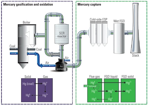
It is well known that increasing the proportion of oxidized mercury (Hg2+) existing in the form of water-soluble mercuric chloride (HgCl2) allows for high Hg emission reduction because HgCl2 can be removed in downstream equipment such as a particulate control device (PCD) and the wet flue gas desulfurization (FGD) system. Therefore, to increase the proportion of Hg2+ upstream of a wet FGD system will facilitate higher overall mercury removal for the plant. Selective catalytic reduction (SCR) catalyst has demonstrated the ability to increase Hg2+ by converting elemental mercury (Hg0) to Hg2+ in coal combustion flue gases.
In general, an SCR catalyst can oxidize elemental form mercury (Hg0) to its oxidized form (Hg2+) in gaseous form and particulate form (Hg(P)); however, the mercury oxidation rate on the SCR catalyst correlates with the SO2 oxidation/conversion rate to SO3 that can cause air heater fouling, flue corrosion, and visible stack plumes. Several downstream SO3 mitigation technologies have become commercially available in recent years, but these systems can have high initial and operating costs, performance limitations, and maintenance concerns. Therefore, an SCR catalyst with high Hg0 oxidation activity and a low SO2 to SO3 conversion rate is economically optimal, especially for U.S. coal-fired plants using high-sulfur coal. (See “SO3’s Impacts on Plant O&M, Part I,” Oct. 2006; “Part II,” Feb. 2007; and “Part III,” Apr. 2007 in POWER’ s archives at https://www.powermag.com.)
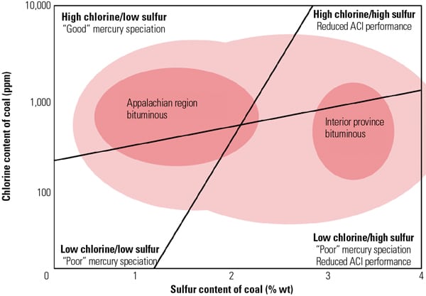
The effect of SCR catalyst on Hg0 oxidation appears to depend on the coal type. Power plants burning high-chlorine (Cl) coals, such as U.S. eastern bituminous coals, tend to show relatively high Hg0 to Hg2+ conversion across the SCR, whereas plants burning low-Cl coals, such as Powder River Basin (PRB) coals, tend to show limited or no Hg0 to Hg2+ conversion across SCR catalyst. In such applications, an enhanced mercury oxidation catalyst capable of achieving higher mercury removal across the plant’s AQCS would be highly desirable. (See “Determining AQCS Mercury Removal Co-Benefits,” July 2010.)
SCR Catalyst Designed to Oxidize Hg
Through extensive research and development, pilot testing, and field demonstration, Hitachi has successfully developed a new type of SCR catalyst, TRAC, which satisfies the high–Hg0 oxidation and low–SO2 oxidation requirements for low-chlorine coal-fired power plants. TRAC has been successfully tested and demonstrated in several slipstream pilot facilities in the U.S. It has been commercially available with full mercury oxidation guarantees since its first installation in a 640-MW PRB-fired U.S. plant in 2008.
Since 2008, TRAC catalyst with high mercury oxidation activity has been supplied to several utilities worldwide, including Southern Company’s Plant Miller Units 1 and 2 and Plant Barry Unit 5.
By adding active catalyst components to conventional catalysts to increase Hg0oxidation activity, the SO2 to SO3 conversion activity will also increase at the same active sites in the catalyst components (Figure 1). The fundamental reaction mechanisms of Hg oxidation and SO2 to SO3 conversion across SCR catalysts were investigated in a Hitachi laboratory to ascertain the most appropriate catalyst composition and manufacturing methods for the new catalyst.
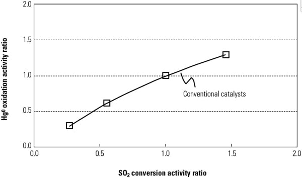 |
| 1. Relationship between SO2 conversion and Hg0 oxidation across activity for a conventional catalyst. Source: Hitachi Power Systems America Ltd. |
Figure 2 illustrates test results for Hg0 oxidation of the TRAC catalyst and conventional catalyst at Hitachi’s Environmental Research Center in Akitsu, Japan. Test results have demonstrated that the Hg0 oxidation activity of TRAC catalyst was 1.4 to 1.7 times higher than that of the conventional catalyst while improving NOx removal activity and maintaining the same SO2 to SO3 conversion activity.
 |
| 2. Hg0 oxidation of TRAC catalyst at the Hitachi pilot-scale test facility. Source: Hitachi Power Systems America Ltd. |
Plant Pilot Testing on PRB Coal
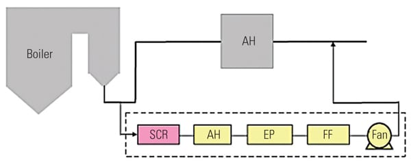
To ascertain the performance of the TRAC catalyst in an actual operating unit, a slipstream reactor (SSR) was installed at a northern U.S. power plant with an SCR system in 2003. The 640-MW plant has a wall-fired boiler and was burning 100% PRB fuel during testing. Following the SCR, the flue gases pass through an air heater, an electrostatic precipitator (ESP), and then a wet FGD system (Figure 3). The testing was conducted from December 2005 to April 2007.
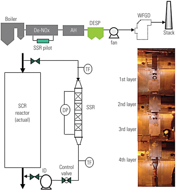 |
| 3. Schematic of SSR test configuration. Source: Hitachi Power Systems America Ltd. |
The SSR, with four layers of TRAC catalyst, designed for 90% NOx removal, was installed next to the existing SCR reactor. The TRAC catalyst is specifically designed for subbituminous fuels containing very low amounts of chlorine. In order to represent actual SCR operating conditions, the inlet duct of the SSR is connected directly to the inlet of the full-scale SCR, just above the first layer of catalyst. This gas contains an adequate amount of ammonia for the de-NOx process, so no halogen injection was used during the testing.
In addition to mercury oxidation, inlet and outlet NOx and ammonia slip are measured simultaneously in order to ascertain the interaction between mercury oxidation and de-NOx at various conditions and time intervals. The commercial ammonia (NH3) injection system placed at the SCR inlet flue was injected at the commercial NH3/NOx mole ratio.
Each layer of SSR catalyst is equipped with air sootblowers, which are operated automatically or at user-specified intervals. The SSR is also equipped with electrical heaters to keep the same temperature across all catalyst layers. An induced-draft (ID) fan and gas flow control damper is provided at the SSR outlet in order to allow adjustment of the amount of gas flow through the SSR. Instrumentation is provided in the SSR at various locations to measure temperature, catalyst pressure drop, and total gas flow. A local control panel is used to provide user interface at the SSR, and a programmable logic controller is included for communication with the plant distributed control system. All of this data is acquired and stored on an hourly basis for future trending and analysis.
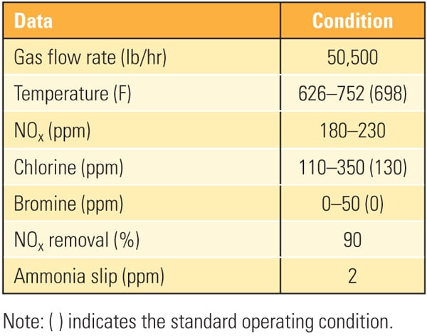
Table 1 show the representative coal and flue gas data from this testing. Based on measurements taken during about 1,000 hours of operation, hydrochloric acid (HCl) concentration in the flue gas was very low (1 to 4 ppm) due to low chlorine content (33 mg/kg) in the PRB coal, which is a good representation case for mercury oxidation for a low-chlorine coal-fired power plant.
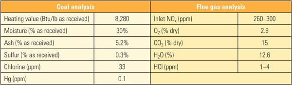 |
| Table 1. Coal and flue gas analysis during slipstream reactor testing. Source: Hitachi Power Systems America Ltd. |
To address the primary objective of this test program, mercury sampling was periodically conducted at test ports throughout the test program. The SSR is equipped with test ports at the inlet, outlet, and an intermediate point for performing measurements using the Ontario Hydro Method. Along with mercury speciation, other measurements simultaneously recorded include HCl concentration at the SSR inlet, ammonia and NOx concentration at the SCR inlet and outlet, and total gas flow. The mercury sampling activities in this test program were divided into five major events: January, April, July, and December 2006 and April 2007. Figure 4 summarizes Hg speciation profiles at each sampling point across the SSR.
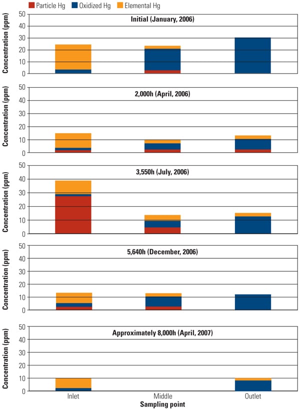 |
| 4. Slipstream reactor mercury speciation measurements. Source: Hitachi Power Systems America Ltd. |
One of the major objectives of this SSR testing is to quantify the mercury oxidation rate over a long period. The SSR demonstration test for the PRB-firing plant showed very good mercury oxidation. It was observed that a significant amount of Hg0 was oxidized to Hg2+ across the catalyst in the SSR for all sampling events, even with very low Hg0 content level at the inlet of the SSR. Hg oxidation capability of the TRAC catalyst remained robust after one year of operation. More than 80% mercury oxidation was achieved across the catalyst in the SSR after 8,000 hours of operation, although HCl concentration in the flue gas for PRB firing was very low.
Figure 5 shows the mercury oxidation rate during 8,000 hours of testing. HCl concentration at the inlet of the SSR was changed with each test run within the range shown in Table 1. Hg oxidation rate for the TRAC catalyst remained high during a one-year test period under low–chlorine level condition, even though the results indicate a gradual decrease in mercury oxidation over time. The mercury oxidation deterioration rate of TRAC catalyst was the same as that for de-NOx. Robust mercury oxidation performance and superior durability of the TRAC catalyst were observed and confirmed through the SSR testing. Therefore, full-scale commercial application of the TRAC catalyst became the next logic step.
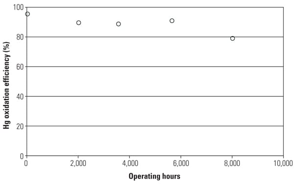 |
| 5. Mercury oxidation efficiency with operating hours at SSR. Source: Hitachi Power Systems America Ltd. |
Pilot Plant Testing at Southern Company
A large-scale pilot test was subsequently conducted at Southern Company’s Mercury Research Center (MRC) using low-sulfur bituminous coal in 2009. This plant is equipped with an AQCS downstream of the SSR, as shown in Figure 6. At the MRC, flue gas is extracted from the outlet of an actual low-sulfur coal-fired boiler and introduced into the SSR-AQCS system by an ID fan, and then returned to the air heater outlet duct. The tested SSR consisted of two layers of full-scale catalyst modules. The flue gas velocities and temperatures were fully controlled during testing. Table 2 shows the mercury oxidation test conditions, and Figure 7 illustrates the outline of the SSR. At this test facility, Hitachi was also able to confirm the performance differences between its typical conventional SCR catalyst and TRAC under actual flue gas conditions.
 |
| 6. Schematic of the pilot test facility at Southern Company’s Mercury Research Center. Source: Hitachi Power Systems America Ltd. |
 |
| Table 2. Test conditions at the Southern Company Mercury Research Center. Source: Hitachi Power Systems America Ltd. |
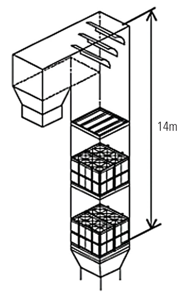 |
| 7. The arrangement of the two layers of catalyst installed during pilot testing at Southern Company’s Mercury Research Center. The catalyst volume was 6.7 m3. Source: Hitachi Power Systems America Ltd. |
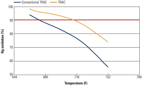
Figures 8 and 9 show mercury oxidation activity for both conventional SCR catalyst and TRAC against halogen concentration and flue gas temperature. As can be seen in both figures, TRAC has excellent mercury oxidation performance at both lower halogen concentration and high flue gas temperature zones compared with conventional catalysts. The results illustrate the superior performance of TRAC under all tested operating conditions.
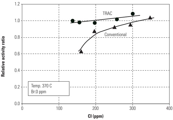 |
| 8. Mercury oxidation activity of the catalyst versus halogen concentration. Source: Hitachi Power Systems America Ltd. |
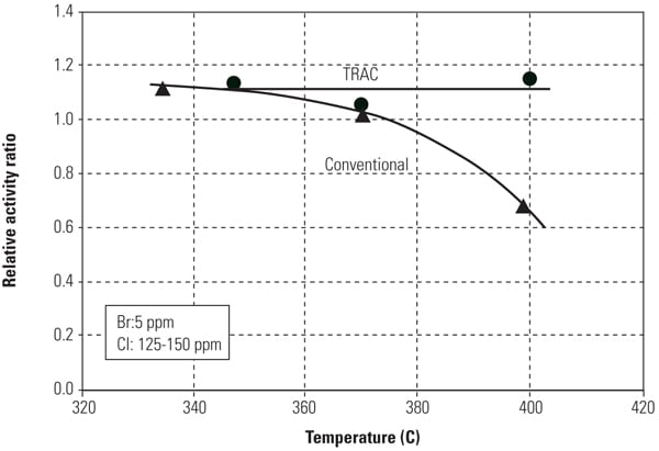 |
| 9. Mercury oxidation activity of the catalyst versus flue gas temperature. Source: Hitachi Power Systems America Ltd. |
Full-Scale Commercial Application
The first commercial application of TRAC involved adding a full layer of catalysts to a full-scale replacement reactor at the same PRB-fired plant where pilot testing had been conducted earlier.
The three-layer replacement reactor consisted of three layers with a spare, empty fourth layer. For testing, the first layer of existing honeycomb catalyst was removed and a layer of TRAC catalyst was installed as the fourth layer. Table 3 shows the coal and flue gas analysis data during testing.
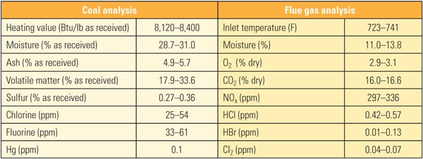 |
| Table 3. Coal and flue gas analysis for first commercial application of TRAC. Source: Source: Hitachi Power Systems America Ltd. |
The TRAC catalyst was supplied and installed in the reactor, and the operation started in June 2008. Hg speciation profiles at the wet FGD inlet and outlet (stack inlet) locations were recorded by using the plant’s mercury continuous emission monitoring (CEM) system. The effect of TRAC catalyst on Hg oxidation was determined by comparing the results during two Hg sampling events, in April 2008 (before TRAC replacement) and in June 2008 (after TRAC replacement). For both events, Hg speciation profiles at the wet FGD inlet and outlet were measured and recorded.
The effect of TRAC catalyst on Hg speciation was determined by comparing the results obtained during the April 2008 sampling event before TRAC replacement (existing three layers without TRAC) and during the June 2008 sampling event after TRAC replacement (existing two layers plus one TRAC layer). Mercury speciation profiles at the wet FGD inlet and outlet for each sampling event are shown in Figure 10.
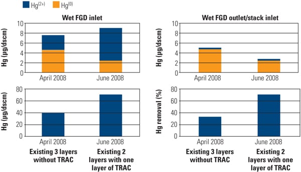 |
| 10. Effect of TRAC catalyst on Hg oxidation and removal across the wet flue gas desulfurization system before and after TRAC replacement. Source: Hitachi Power Systems America Ltd. |
The presence of TRAC catalyst significantly affected the Hg speciation profile at the inlet of the wet FGD system. In the absence of TRAC catalyst (existing three layers without TRAC), the ratio of Hg2+/Hg (total) at the inlet of the wet FGD averaged about 40%. The presence of TRAC catalyst increased this ratio to about 70%. By observation, the presence of the TRAC catalyst significantly increased Hg2+ level at the inlet of the wet FGD system.
As a result of the increased Hg2+ at the wet FGD inlet, total Hg removal across the wet FGD increased from 30% (before TRAC replacement) to 70% (after TRAC replacement). Results from the full-scale application are in good agreement with SSR testing results and demonstrate that the Hg0 oxidation activity of the TRAC catalyst was significantly higher than that of the conventional catalyst with low-chlorine coal. Figure 11 presents the Hg CEM results before and after TRAC replacement.
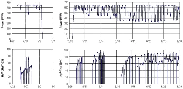 |
| 11. Mercury CEM system data collected before (left column) and after (right) one layer of TRAC replaced a conventional layer of catalyst. Source: Hitachi Power Systems America Ltd. |
The superior performance benefits of TRAC have been demonstrated, but what about the costs? The economics of adding TRAC catalyst are illustrated in Table 4. For most eastern bituminous coal applications, the existing catalyst is sufficient to oxidize the mercury. However, some units can benefit from an extra boost of mercury oxidation with one or two layers of TRAC. For PRB applications, TRAC can help to minimize the amount of ACI required and thereby save the cost of mercury oxidation.
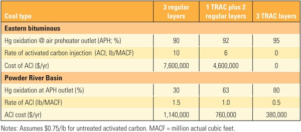 |
| Table 4. Economics of TRAC catalyst for a typical 680-MW unit. Source: Hitachi Power Systems America Ltd. |
The most cost-effective mercury control strategy is to use existing equipment in order to comply with new standards. In particular, Southern Company has evaluated mercury oxidation across catalysts with enhanced mercury oxidation, such as TRAC. This strategy requires that the oxidation be maintained across a range of temperatures, fuel halogen contents, and NOx control levels. Such a catalyst would allow utilities to reduce or eliminate the need for halogen injection and simultaneously comply with stringent NOx emission standards.
Based on pilot-test results, Southern Company moved forward with full-scale applications of TRAC catalyst at several generating facilities burning PRB and bituminous fuels.
— Anthony C. Favale, PE (anthony.favale@hal.hitachi.com) is the director of SCR products; Stephen Guglielmo (stephen.guglielmo@hal.hitachi.com) is the northeast sales manager; and Dr. Peter Jin, PE (peter.jin@hal.hitachi.com) is SCR engineering manager for Hitachi Power Systems America Ltd. Yoshinori Nagai (yoshinori.nagai.kw@hitachi.com) is the general manager of reserch and development for Babcock Hitachi, K.K., Japan. Dr. Corey A. Tyree (catyree@southernco.com) is a project manager in Southern Company’s Research & Environmental Affairs Group in Birmingham, Ala.