The power generation industry is among those whose aging infrastructure contributes to increased safety concerns, and can lead to costly unscheduled maintenance and shutdowns. Facilities must be vigilant about monitoring corrosion in their in-service pipes and vessels to help ensure their integrity. To correctly assess the damage and to wisely invest in their infrastructure, the industry needs inspection solutions that provide:
■ Productivity
■ High-density and high-quality data
■ Low cost
■ Ease-of-use
■ Portability
■ Reliability
■ Safety
■ Recordable, easy-to-interpret imaging
 |
|
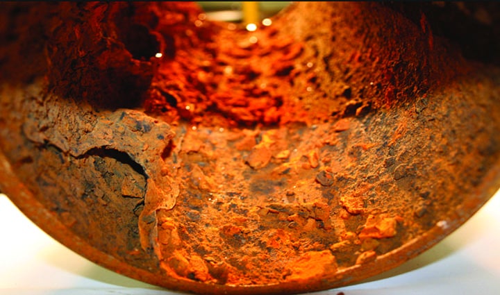
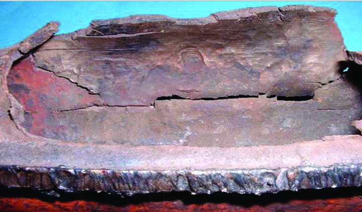
1. General corrosion, in this case caused by erosion, is a problem in many older pipes and other vessels that hold fluids in power generation facilities. Courtesy: Olympus |
 |
|
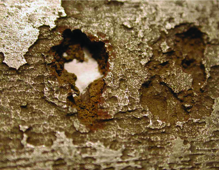
2. Microbiological-induced corrosion literally eats away at pipes and other equipment, particularly in aging facilities. Courtesy: Olympus |
Inspectors need reliable and effective tools that can assist them in accurately detecting deterioration before it becomes too severe. Corrosion can appear in several forms, owing to the different physical forces and fluids that have an impact on power generation assets. Some examples of the types of corrosion that can impact aging pipes and vessels include generalized corrosion (Figure 1), microbiological-induced corrosion (Figure 2), pitting corrosion (Figure 3), and high-temperature hydrogen attack (HTHA, Figure 4).
 |
|
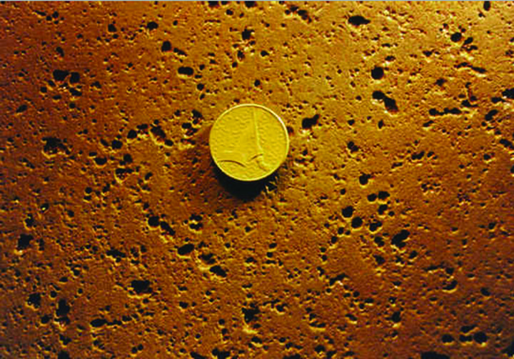
3. Pitting corrosion leaves its mark on pipes and other equipment and can lead to larger problems. An ultrasound inspection can reveal a material’s thickness and help power plant operators understand the depth of an equipment issue. Courtesy: Olympus |
 |
|
4. This photo shows the damage caused to equipment by a high-temperature hydrogen attack. Courtesy: Olympus |
Technology that facilitates corrosion inspection already exists, but there is a new tool that can offer key improvements by combining advantages of two common techniques: conventional pitch-catch ultrasound and phased array. This new technology is called the dual linear array probe, and it was the limitations as well as the advantages of these ultrasound-based techniques that motivated its development.
Applying Ultrasonic Technology to Corrosion Inspection
Ultrasonic corrosion mapping inspection is a key aspect of infrastructure integrity programs. This technique enables inspectors to measure and record variations in the thickness of the pipe or vessel wall to monitor the progression of corrosion over time.
Using conventional ultrasonic testing (UT) is a common way to measure a material’s thickness. It can be easily done on in-service equipment because UT instruments are portable, and the method is a nondestructive test (NDT).
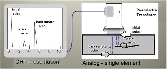
The basic principle of ultrasound inspection is that a transducer comprised of a piezoelectric crystal sends ultrasonic sound into the material, receives the reflected sound wave, and then converts it into an electrical signal that the instrument can process. The velocity of the ultrasound is dependent on the type of material, so by knowing this velocity and measuring the time from the moment the ultrasound is sent to the moment it is received, the instrument can calculate the depth or position of a flaw.
The shape and orientation of the flaw have an impact on the strength or amplitude of the returned signal. The ideal scenario is when the ultrasound hits the flaw perpendicular to its surface, enabling the maximum amplitude of the signal to be returned to the transducer. Alternatively, if the sound is deflected away from the transducer, then little to no signal can be measured.
 |
|
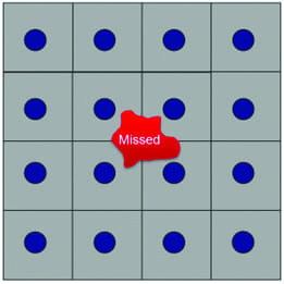
5. There are several disadvantages of manual ultrasonic thickness gaging, including missing flaws that lie between the grid points. Courtesy: Olympus |
One challenge of inspecting for corrosion with ultrasound is that the damage is typically rounded and irregular shapes that reflect the sound in many different directions, so only part of the energy is reflected back toward the transducer. Making a correct assessment of the condition is difficult if you’re taking single-point measurements with a transducer as it may only provide partial information (Figure 5).
Limitations of Manual Thickness Gaging with Dual-Element Transducers
For ultrasonic thickness gaging applications such as corrosion monitoring, the transducer uses longitudinal waves (or compression waves), and the measurement is performed from one side of the part. A dual-element transducer is often used to isolate the transducer’s pulser from the receiver, helping to minimize the interface echo to improve the detection near the surface.
 |
|
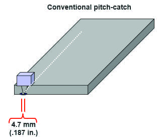
6. The range of frequencies typically used in a pitch-catch inspection is between 0.5 MHz and 10 MHz, and the operator must check the component point by point inside a grid. Courtesy: Olympus |
The range of frequencies typically used with this dual-element pitch-catch inspection (Figure 6) is between 0.5 MHz to 10 MHz, and the operator spot checks the component, point by point inside a grid, to find the minimum thickness. The results of this method are highly dependent on the operator’s abilities and are difficult to replicate from one operator to another or even from day to day.
The disadvantages of manual ultrasonic thickness gaging typically include:
■ Long and demanding process
■ Results are less reliable because a flaw can be missed if it lies between the grid points
■ Operator dependent, permanent recording is not integrated into the process
■ Limited use of the data for mechanical engineers
■ Inconsistent probability of detection
Upsides of Automation—and the Downsides
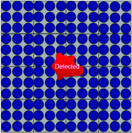
For inspectors, the main issues with thickness gaging using conventional UT are that it’s time-consuming, has a low data density, and it cannot be effectively used to monitor corrosion because the data is captured periodically and cannot be directly compared with previous results. Automating the inspection can partly resolve these problems. When an automated scanner is used with a UT probe or transducer, it can take measurements in a raster pattern to improve the data density (Figure 7).
 |
|
7. An automated scanner, used with an ultrasonic testing probe or transducer, can take measurements in a raster pattern to improve the data. Courtesy: Olympus |
However, automated UT inspection has limitations of its own, such as low productivity due to the transducer’s limited coverage. Each line of the scan inspects only a few millimeters at a time. To completely inspect the delimited area, multiple back-and-forth movements are necessary. Also, the scanner’s fast mechanical movements contribute to additional issues, including:
■ Security concerns for operators
■ Prone to scanner failures
■ Coupling becomes difficult at high speed, leading to unreadable data points
Advancing Automated Corrosion Inspection Through Phased Array
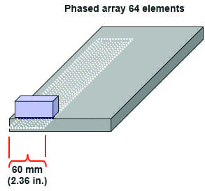
When incorporated into an automated scanner configuration, phased array technology can further improve the effectiveness, reliability, and safety of the inspection. Phased array (PA) probes (Figure 8) are composed of multiple piezoelectric elements. Pulsing and receiving of the elements are electronically controlled to generate beams that are focused at a specific depth in the part.
 |
|
8. Phased array probes contain multiple piezoelectric elements. This illustration shows a phased array testing coverage area. Courtesy: Olympus |
PA automated scanning can provide:
■ High productivity
■ Large-area coverage in one acquisition
■ High point density
■ Slow mechanical movements
■ Full volumetric representation
■ Data archiving
■ Usable offline data, even by non-NDT engineers
■ Compatibility with any mechanical properties and stress analysis tools
Corrosion inspection with a phased array probe is performed using what is called a linear scan, which helps increase the overall efficiency by exploiting the full width of the probe. Safety is less of a concern with an automated inspection configuration that uses phased array probes because the scanner can move at a slower speed while still increasing productivity. For example, a 406-millimeter (mm, 16-inch) outside diameter pipe with a wall thickness of 9.5 mm was scanned with 100% coverage and a resolution of 1 mm × 1 mm at a scanning speed of 100 mm/second (4 in./sec.). The scan took a total of three minutes.
To help optimize the automated PA solution, the data acquisition instrument must meet the following requirements:
■ Phased array capability
■ Two-axis encoding enabled
■ Easy to operate to increase the pool of operators and not be limited to one expert
■ Multiple visualizations of the acquisition to boost the probability of detection
■ Ability to save, store, and recall acquisition files to monitor the evolution of corrosion over time and for audits
Combining the Advantages of Dual Element UT and Phased Array in One Probe
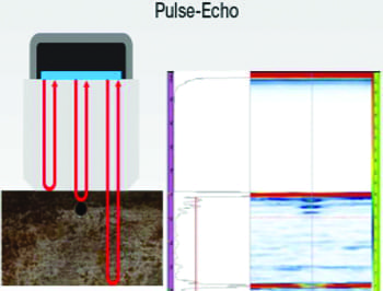
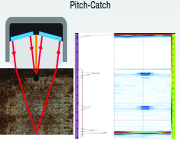
While standard phased array proposes a pulse-echo approach (Figure 9), the signal can be improved, and you can achieve a near-surface resolution that is similar to that of UT pitch-catch (Figure 10) transducers, if you apply the same technology that separates the transmitter and the receiver to phased array probes.
 |
|
9. Standard phased array probes utilize a pulse-echo approach. Courtesy: Olympus |
 |
|
10. The signal in a standard phased array design can be improved by applying the same technology that separates the transmitter and the receiver in pitch-catch transducers. Courtesy: Olympus |
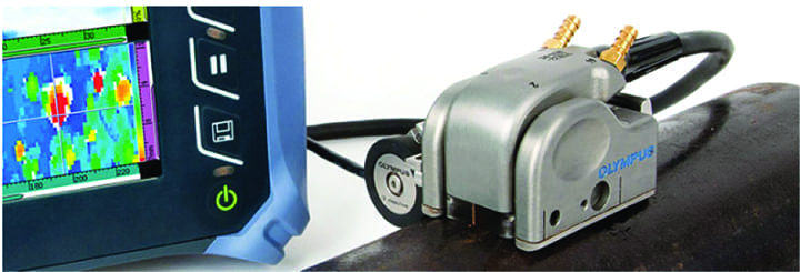
The dual linear array (DLA) design incorporates two arrays of elements yet separates them with an acoustic barrier, so they can be used in pitch-catch mode like a UT dual-element transducer. There are five main advantages of the DLA probe (Figure 11) for corrosion inspection.
 |
|
11. The dual linear array probe provides advantages for corrosion inspection, including a larger beam coverage. Courtesy: Olympus |
Larger Beam Coverage. Inspectors can increase productivity and the probability of detection with the DLA probe’s wider beam coverage. While the width of a typical UT probe’s inspection beam is 4.7 mm (0.19 in.), making it useful for spot checks only when used manually, DLA probes have a beam width of 30 mm (1.18 in.), so a large area can be inspected quickly. It is, therefore, possible to generate a C-scan with a higher likelihood of detecting small flaws.
Locate Smaller Defects. When using the conventional UT method to monitor corrosion, inspectors take manual point thickness measurements on the pipe (spot checks), typically using a 1-square-inch grid. However, this can cause inspectors to miss smaller defects that fall between the point measurements.
The smaller elements used in DLA probes help inspectors perform high data-point density inspections faster than what can be accomplished using conventional dual UT probes. With a higher point density, you can reduce the chances of missing small defects.
Better Near-Surface Resolution. DLA probes employ the pitch-catch technique for increased near-surface resolution as compared to phased array probes that use pulse-echo mode. DLA probes have a minimal interface echo, enabling inspectors to locate flaws as close as 1 mm (0.046 in.) from the surface. This feature is essential for locating critical defects such as wall thinning and pitting.
Corrosion Scanning Made Easy. The probe can be used for encoded data acquisition using the mini-wheel encoder or any Olympus scanner and comes supplied with OmniScan setup files, so you can start your inspections quickly with minimal setup time.
Thanks to enhanced features, such as built-in irrigation and a replaceable delay line that can be contoured to better adapt to pipe curvature, the DLA corrosion probe can also be used to perform semi-automated inspection using the MapSCANNER or automated inspection using the MapROVER with improved sound transmission and no headaches having to deal with couplant.
Reliable and Versatile. On top of a replaceable delay line, DLA corrosion probes feature a carbide wear plate for extra protection. The probe also features an integrated stabilization system with a quick radius adjustment for increased stability on curved surfaces with a 4-inch outside diameter all the way up to flat surfaces. ■
—Simon Alain is product manager, Scanners and Inspection Solutions,
for Olympus.