Low power factor reduces an electrical system’s distribution capacity by increasing current flow. Therefore, having a low power factor is inefficient and expensive. But what is power factor and what affects it?
A typical distribution system is limited in the amount of current it can carry; power factor, expressed as a percentage, is an indicator of the amount of total current that can be used to create work (active power). The closer the power factor is to 1.00 (100%), the lower the amount of current needed to do said work.
For example, a load with a power factor of 0.80 means that only 80% of the power is being used effectively to do work. In a perfect world, all power drawn from the power system would be converted to useful work, but this is not so in the real world. To fully describe power factor, complex equations are needed. For a simpler understanding, though, the U.S. Department of Energy uses a simple analogy of the power required for a horse to pull a trolley down a track.
Ideally, the horse would be placed in front of the railcar to provide the most-efficient towing force; however, that isn’t always possible. The angle of the tow represents the change in power factor—the smaller the angle, the better the power factor, the larger the angle, the lower the power factor (Figure 1).
 |
| 1. Angles affect useful work. The analogy shown here provides a visualization to help understand power factor. Power factor is defined as the ratio of real (working) power to apparent (total) power. If the horse is led closer to the center of the track, the angle of side-pull decreases, and the real power approaches the value of the apparent power. Source: U.S. Department of Energy |
The total energy required to pull the railcar is apparent power. The actual energy moving the railcar is real power. The energy not used from the pulling angle of the horse is reactive power. In other words, real power, also referred to as working power (kW), performs the actual work of motion, heat, and light. Reactive power, or nonworking power (kVar), sustains the magnetic field of a reactive load (usually inductive). The current used to create the reactive power is not used to create work; however, this current places a burden on the distribution system, the electric supplier, and a facility’s electric bill.
The vectoral sum of working power and nonworking power is total power (apparent power):
Apparent power = √ (Real power2 + Reactive power2)
which is used to calculate power factor:
Power factor = Real power / Apparent power = cosine of the angle (ϕ)
Voltage and Current Fundamentals
To understand power factor, we must first understand some basic alternating current (AC) theory and the waveforms associated with it. The voltage in an AC system alternates between positive and negative (in a sinusoidal shape) and forces the current to behave similarly. This occurs 60 times per second (in a 60-Hz system), ranging from 0 to 360 degrees. Unlike AC systems, the voltage in a constant direct current (DC) system does not change.
Because the instantaneous value of the AC voltage is continuously changing, science has defined a different measure for AC quantities, namely the RMS (root mean square) value. The RMS value of an AC waveform produces the same heating effect as a DC waveform of the same value.
The RMS is the square root of the arithmetic mean of the squares of a set of the instantaneous values over a period (cycle). When the voltage and current are purely sinusoidal, the RMS voltage and current can be found from the peak (pk) voltage and current:
VRMS = Vpk / √2
119.5 VRMS = 169 Vpk / 1.414
Similarly,
IRMS = Ipk / √2
75 ARMS = 106 Apk / 1.414
You may be asking yourself, what does this have to do with power factor? Power calculations for AC require knowledge of RMS voltage, RMS current, and the sinusoidal phase relationship. So, to summarize, RMS is a measure of the heating effect, calculated from a waveform, which allows the comparison of AC to DC. Any phase shift from a pure sinusoidal waveform indicates power factor.
The following is a comparison of how power factor affects output kVA on two different single-phase loads.
For a 9-kW electric space heater (120 VAC, 75 A) with 1.0 input power factor (PF):
P = √1ϕ x 120 VAC x 75 A x 1.0 PF = 9 kW
kVA = √1ϕ x 120 VAC x 75 A = 9 kVA
For a 9-kW battery charger (120 VAC, 75 A) with 0.866 input PF:
P = √1ϕ x 120 VAC x 86.6 A x 0.866 PF = 9 kW
kVA = √1ϕ x 120 VAC x 86.6 A = 10.392 kVA
Although each load consumes 9 kW of power, the battery charger’s input power factor is 0.866. The lower power factor requires an additional 11.6 A to operate, which is eventually provided by the power company. Not only must the additional reactive current be purchased, but also the size of the distribution system must be increased to handle the additional current.
What Affects Power Factor?
Power factor refers to the relationship between active (useful power) and the apparent (total) power. This relationship is a measure of how effectively electricity is being used.
Linear Resistive Loads. In an AC system, loads are categorized by the way they draw current. A linear resistive load is a purely resistive load with neither inductive nor capacitive components, such as electric space heaters and incandescent lighting. The voltage and current curves intersect the zero coordinate at the same point.
The power curve (P) in Figure 2 is calculated by the voltage (V) and current (I), shown as the positive area of the graph. In this example, the voltage and current are 120 VRMS and 75 ARMS, respectively. The product of the two is 9 kVA or 9 kW. The voltage and current are “in phase,” and 100% of the power (working power) is being used effectively to do useful work. The power factor for this type of load is 1.0.
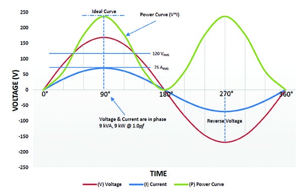 |
| 2. Linear resistive loads. Voltage and current are in phase with power factor equal to 1.0 for purely resistive loads. Courtesy: Ametek Solidstate Controls |
Linear Non-Resistive/Reactive Loads. It is unusual to find purely resistive loads; most loads have an additional reactive component. These non-resistive/reactive loads make up a large percentage of all loads. The current waveform is shifted from the voltage waveform so that it is “out of phase.” If the load is inductive, the current lags the voltage; if the load is capacitive, the current leads.
Industrial facilities tend to have lagging power factor loads (inductive loads). These types of loads can be induction motors, chokes, and transformers. Leading power factor loads (capacitive loads) are less common and are usually underground cables or certain switch-mode power supplies.
In Figure 3, the same load from Figure 2 now has the voltage and current waveform out of phase by 30 degrees. Because this is an inductive waveform, the current is now lagging.
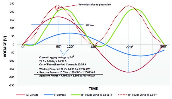 |
| 3. Inductive loads. Voltage and current are out of phase for linear non-resistive/reactive loads. In this inductive load example, current lags voltage by 30 degrees with power factor of 0.866. Courtesy: Ametek Solidstate Controls |
Non-Linear Loads—Harmonics. Today’s industrial settings not only have resistive, inductive, and capacitive loads, but many also include solid state-based equipment, such as switching power supplies, DC drives, variable-frequency drives (VFDs), electronic ballast, arc welders, and temperature-controlled ovens. These are all non-linear loads, or loads for which the current is non-sinusoidal, even when the voltage is sinusoidal. The non-sinusoidal nature of these waveforms is expressed using harmonics.
Harmonics are waveforms of varying amplitude at frequencies that are multiples of the fundamental frequency of the voltage (50 Hz or 60 Hz). They are superimposed onto the sinusoidal waveform of the current to create the total current waveform. Figure 4 is an example of such a current waveform.
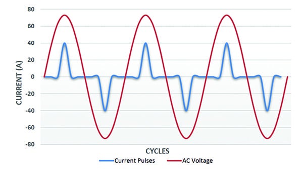 |
| 4. Non-linear loads. This graph shows the voltage and current waveforms of a non-linear power supply with harmonics. It is shown without a 30-degree current phase shift for clarity. Courtesy: Ametek Solidstate Controls |
The RMS value of the entire current is found by summing the RMS value of each harmonic current. Given a 60-Hz waveform, this means a 2nd harmonic frequency would be 120 Hz (60 Hz x 2 = 120 Hz) and the 3rd, 4th, and 5th harmonic frequencies would be 180 Hz, 240 Hz, and 300 Hz, respectively. As multiples of the fundamental frequency, harmonics can be expressed as 2f, 3f, 4f, etc.
The current total harmonic distortion (THD) is the summation of all harmonic components of the current waveform compared against the fundamental component of the current wave. As shown below, it is a ratio of the RMS value of the harmonics of the current to the RMS value of the fundamental current.
ITHD = RMS of current harmonics / RMS of fundamental current = √(I22 + I32 + I42 + …) / I1 x 100%
For purely sinusoidal waveforms, the phase shift between voltage and current is sufficient to quantify the power factor (PF). For waveforms that are not sinusoidal, the term displacement power factor (DpPF) is used to quantify the phase shift between the fundamentals of the two waveforms (the 50-Hz or 60-Hz components). For the same non-sinusoidal waveforms, a term is defined to quantify the effect of the harmonics over the PF. This term is called the distortion power factor (DF).
DF = 1 / √(1 + THD2)
To find total power factor (PFT), the following equation is used:
PFT = DF x DpPF
Correlations of Power Factor
For linear loads, the power triangle is a right triangle that shows the relationships between working, reactive, and apparent power. The relationship between working and apparent power is PF. The value can range from 0.0 to 1.0.
Working power, also called true power, real power, or active power, performs the actual work of motion/heating/lighting etc. and is measured in watts (W). Reactive power sustains the magnetic or electric field in devices, such as solenoid coils, motor windings, transformer windings, capacitors, and ballasts, without doing actual work. This extra energy is measured in volt-amperes reactive (VAR) and is sometimes called “wattless” power. Apparent power combines working power and reactive power, and is measured in volt-amperes (VA).
The phase angle (ϕ) in degrees, represents the “inefficiency” of the load and corresponds to the total reactive impedance (Z) to the current flow in the load. The larger the phase angle, the greater the reactive power. Non-linear loads add an extra element to the total (apparent) power without adding to the active power, further decreasing the power factor. ■
—David McKinnon is senior applications engineer with Ametek Solidstate Controls. Special thanks to Bogdan Proca, PhD and Doug King for their contributions.