There are challenges to adding power generating capability to a dam built for flood control, but the Red Rock Hydroelectric Project shows that the obstacles are not insurmountable. With the right team, success is achievable.
Conventional hydropower produced about 7.25% of the total electricity generation in the U.S in 2020. Yet, only about 3% of the roughly 80,000 dams installed in the U.S. generate electricity. Many of the non-powered dams were constructed for purposes such as recreation, stock/farm ponds, flood control, water supply, and irrigation. Many are small, and, in most cases, it would be impractical to add power generation to them. However, there are exceptions. The Oak Ridge National Laboratory conducted a study and found that adding electricity generating capability to the 100 largest non-powered dams could provide 8 GW of new hydropower—essentially, the “low-hanging fruit.”
The Red Rock Hydroelectric Project
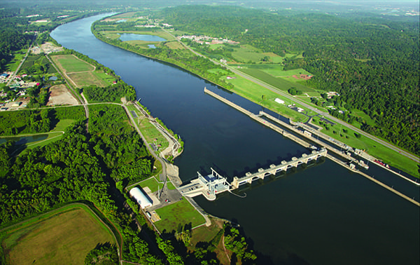
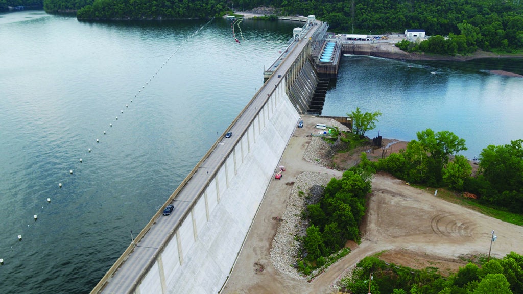
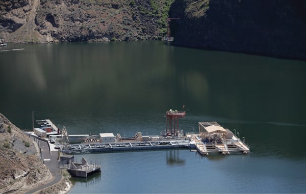
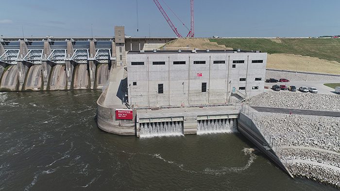
The Red Rock Hydroelectric Project (RRHP) on the Des Moines River, about 2.5 miles southwest of Pella, Iowa, is one example of just such a project. The Red Rock Dam was constructed by the U.S. Army Corps of Engineers (USACE) in 1969 for flood control, which remains the dam’s primary purpose today.
Missouri River Energy Services (MRES)—a 61-member organization of municipalities spread across Iowa, Minnesota, and North and South Dakota—made the decision to add power generation to the existing Red Rock Dam based on its desire to supply clean, reliable, cost-effective, long-term renewable electricity to its members. The successful project is a 2021 POWER Top Plant award winner in the Renewable Energy category. It now operates on a “Run of Release” basis as directed by the USACE, so as not to affect the flood control operations for the Des Moines River.
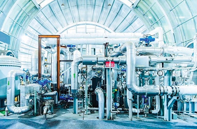
After acquiring the Federal Energy Regulatory Commission license from the original project developer, MRES awarded a design contract to Stantec in 2011. Stantec (formerly MWH) was the Engineer of Record for the plant (from the intake structure to the tailrace). Other companies that played major roles in the development and construction of the RRHP include DGR Engineering (Engineer of Record for the substation, transmission, and utilities), Voith Hydro (equipment manufacturer for the turbines [Figure 1], generators, and balance-of-plant systems), Ames Construction (general contractor for project construction), and Rockwell Automation (Allen-Bradley programmable controllers for the plant control system). The project was developed using a hybrid “design-bid-build” approach in which the engineers completed much of the design, including temporary structures, while leaving the detailed design of mechanical and electrical systems to the contractor.
 |
|
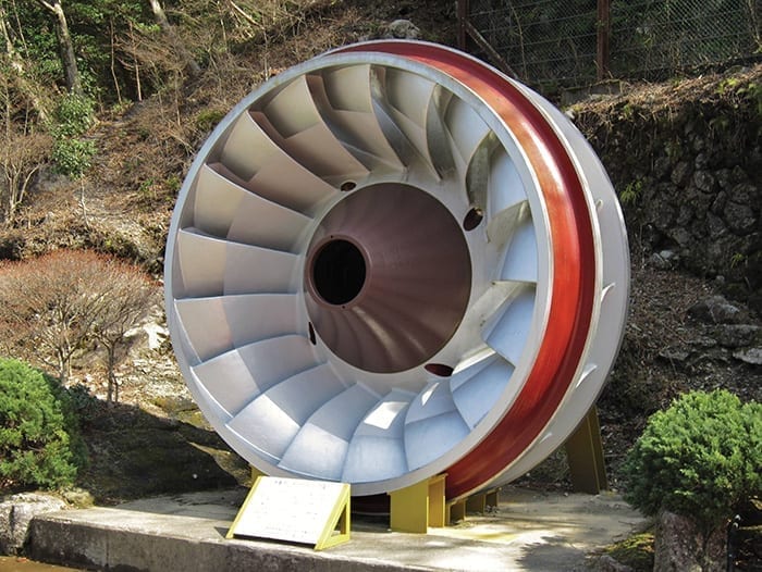
1. The Red Rock project has two vertical-shaft, single-runner, Kaplan-type hydro turbines with adjustable runner blades and wicket gates. Each unit has a rated turbine output of 21.6 MW while operating at the rated speed and design net head of 62.1 ft. Courtesy: Missouri River Energy Services |
A Challenging Project
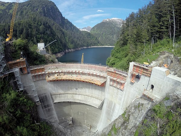
“Constructing a project immediately adjacent to an operating spillway presented significant challenges,” Tom Andrews, vice president of Power and Dams with Stantec, told POWER. “Construction of the permanent works required upstream and downstream cofferdams, and several excavations up to 70 feet deep into the existing dam and its foundation, plus penetrations through the existing concrete gravity monolith. The intrusive nature of the work required that steps be taken during construction to reduce potential impacts to the dam’s integrity and to maintain dam safety.”
As the project engineer, Stantec prepared designs for all the temporary works, and construction sequence drawings were developed to prescribe the staged construction of the project. The sequence defined by those drawings became part of the design criteria for the final design of the temporary and permanent structures, as they outlined the loading conditions during each phase of construction.
Excavation support systems were designed to minimize deformations and the potential for construction-induced cracking of the embankment, and a concrete diaphragm wall along the axis of the dam was designed as a seepage cutoff. Additionally, a rigorous surveillance inspection and instrumentation monitoring program was implemented to evaluate the performance of the dam, as well as the temporary and permanent works, during and after construction.
“Prior to the start of construction, there were no flat or gently sloping areas available from which heavy equipment could operate, nor vehicular access to the area of the future intake structure, which complicated the construction of the earth retaining features. Temporary work platforms and access roads had to be constructed on the upstream face of the dam to facilitate the work,” Andrews said.
The construction of the upstream diaphragm wall, which is one of the largest walls of its type in the world, presented unique challenges. Given the confined working area, careful oversight was needed to stage the work properly. For example, transporting the 130-foot-long, 90-ton reinforcing cages to the work zone, executing critical lifts to take the cages from horizontal orientations to vertical, and then positioning the cages for installation in the diaphragm wall required significant coordination. Quality control of the specialty concrete mixes, welding, and other project components was also critical for successful completion of the project.
Design and Implementation
The RRHP’s upstream diaphragm wall along the new intake channel supports a 69-foot-tall cut in the embankment dam without anchors and was designed to minimize deformations that could otherwise potentially induce cracking of the dam’s clay embankment. The wall was constructed using abutting T-shaped elements up to 130 feet tall. These heavily reinforced elements included five-foot-wide stems that extended 16 feet into the embankment from the back of the five-foot-thick face of the diaphragm wall, which made the T-shaped wall elements a total of 21 feet across.
The construction sequence for each T-shaped element required three overlapping passes—or “bites”—of a hydromill trench cutter to achieve the design geometry. Each bite consisted of a vertical pass of the 10.5-foot-long by five-foot-wide hydromill cutter head from the ground surface to the bottom of the rock socket. The rock embedment depth of the upstream diaphragm wall was established to minimize deformations and extended up to 35 feet. A self-consolidating tremie concrete mix with an initial set time of 16 hours and negligible bleed was developed to facilitate the extended duration required to place concrete for each T-shaped element.
“Each of two intake openings are fitted with a wheel gate capable of closing against flow for protection of the unit,” said Andrews. “The feature is vital in the event of a turbine runaway speed condition due to failure of the turbine wicket gates to close and also in the event of a penstock rupture.”
The gates are vertical-lift, fixed-wheel gates and each closes an opening approximately 18 feet wide by 21 feet high. The wheel gates are also capable of closing the intake under balanced pressure when necessary for turbine maintenance and were used to close the intake water passages during construction of the penstock dam penetrations.
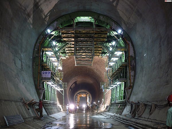
Two circular reinforced concrete penstocks with 21-foot interior diameters convey water from the intake structure to the powerhouse. The two penstocks are sized to provide a velocity of 7.7 feet/second at a full flow of 10,235 cubic feet/second.
At the intake structure and powerhouse connections, the penstocks transition to a rectangular section. The two penstocks penetrate through the concrete gravity dam monoliths adjoining the spillway. The penstocks are steel-lined downstream and designed to withstand operating pressure—including transient pressures from a load rejection of the units—and to resist buckling when unwatered.
Penstock construction required excavations up to 70 feet deep within the existing dam and its foundation. In addition to the importance of minimizing deformations to maintain the integrity of the existing dam, the design of the excavation support systems had to account for the differential loading from the embankment dam slopes.
The extensive excavation support included braced excavations supported by steel combi-walls (sheet piles interlocked with steel beams). The penstocks penetrated through two adjoining concrete gravity dam monoliths immediately adjacent to the spillway. Wire-saw cutting was used for each of the 24-foot-wide octagonal penetrations through the concrete dam monoliths, which were designed to be self-supporting during construction.
 |
Successful Completion
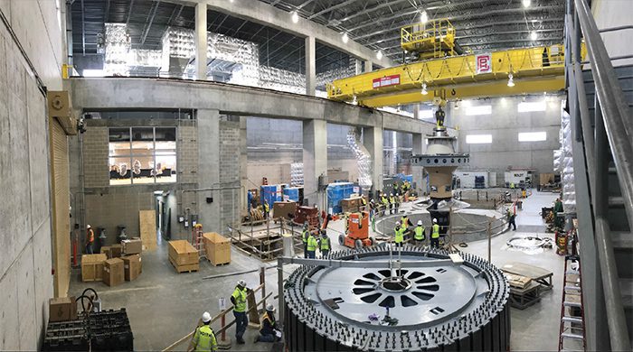
Design work began in 2011, but the construction contract and onsite work did not start until 2014. During the RRHP, more than 2.3 million onsite worker hours were logged, with about 175 workers involved at the height of construction. Skilled laborers and operators were hired out of the local union hall to complete all necessary tasks, and 39 separate contractors were utilized during the project. The overall job incident rate was 1.9, which compares favorably to the national average (2.8). At least some of that safety success can be attributed to pre-activity meetings that were regularly held by the engineer with contractor teams prior to significant and/or particularly challenging tasks.
Engineers were surprised by one discovery early in the construction phase. “While grouting around the land-side perimeter during routine pre-excavation work, the construction team encountered a voided zone in the rock created by previously undetected gypsum,” said Andrews. “The voided zone had originally been partially infilled with soil and rock fragments, but it was still characterized by artesian flows. These flows came from grout holes and reached volumes of 20 gallons per minute and higher.” The solution involved a combination of extensive cement and chemical grouting to treat the voided rock.
The RRHP also experienced extensive flooding of the upstream work during construction, which delayed completion. Periods of high water were expected, but it was not practical to construct a cofferdam to protect against the full range of possible fluctuations. The reservoir level in 2018 and 2019 exceeded expectations and remained elevated for several months. Stakeholders worked together to mitigate and manage the issues, avoiding unnecessary cost and time extensions, and also minimizing the collateral effects to other portions of the work.
Wet commissioning of turbine generator units was completed in July 2020, and substantial completion of the project was acknowledged on Sept. 2 that year. The facility was declared commercially complete on June 10, 2021.
—Aaron Larson is POWER’s executive editor.