Many combined cycle power plants are being operated as peaker plants, rather than as baseload units. That can pose a problem for economizer safety valves. Pilot-operated safety valves offer several advantages compared to standard spring-loaded safety valves in this situation.
The power industry has witnessed a series of major technology shifts over the past few decades, from a 20th-century infrastructure that was dominated by coal-fired and nuclear plants to the more-efficient and environmentally friendly supply of power that exists today. A major reduction in the cost of natural gas drove the rapid emergence of combined cycle power plants (CCPP) that yield higher efficiencies coupled with a smaller carbon footprint. For nearly 20 years, CCPPs have been the dominant technology with new construction and surging capacity around the world.
More recently, however, reduced generation costs, shorter construction lead-times, and government subsidies have given renewable energy sources, such as wind and solar power, a surge in global demand. Rampant growth of renewable power has dramatically reduced the demand for new CCPPs. According to the International Energy Agency, 2015 marked a turning point for renewables. Led by wind and solar, renewables represented more than half of all new power capacity installed around the world that year, and the growth has continued.
The increase in total market supply capacity, along with the lower operating cost of renewables, has led the power industry to transform many CCPPs into “peaker” units to supply power when renewable sources cannot meet full demand, such as when the sun goes down at night. This change in demand has driven CCPPs to alter their operations for rapid generation availability, which translates into faster startup and shutdown, and heavy cycling load on major equipment, such as heat recovery steam generators (HRSGs).
Economizer Application
As a CCPP comes online, feedwater temperature is elevated as it absorbs heat from the gas turbine exhaust through a system called the economizer before it is fed to the HRSG where it fully transforms into steam to drive the steam turbine. The economizer itself is designed as a fired pressure vessel, and as such, is required by ASME code to have one or more pressure relief devices in the event it becomes isolated from the boiler and needs to exhaust independently.
Historically, these pressure relief devices have been direct, spring-loaded, closed-bonnet-type safety valves. These spring-loaded safety valves are required to be certified to ASME Boiler and Pressure Vessel Code (BPVC) Section I rules, which means these valves are required to be designed, tested, and certified with steam as the fluid media. However, the economizer application fluid is commonly high-temperature water that has not yet fully undergone a phase change into steam.
This presents a paradox for code design versus suitable application engineering, as code-required steam trims are not designed to relieve in liquid applications. In many installations, these spring-loaded steam safety valves result in a common relief scenario called “chatter.” Chatter is a vibration effect induced by a continuous series of rapid opening and closing events. If left unaddressed, chatter can quickly lead to damage and leakage across the valve seat, and if severe enough, can even result in damage to adjacent piping.
In response to this trend of damaged spring-loaded economizer valves and well-documented HRSG startup issues, the ASME BPVC Section I committee prepared and approved Code Case 2446, allowing pilot-operated safety valves (POSV) to be used to protect the economizer. The POSV has many advantages over a spring-loaded valve in this application, including the following:
- ■ POSVs can operate closer to set pressure without seat leakage.
- ■ POSVs have shorter blowdown, which is the difference between the set pressure and closing pressure; thus, reducing the amount of steam lost from the system during an excursion.
- ■ POSVs are typically not trim dependent, meaning they operate equally with either a liquid or steam relief condition.
POSVs operate by sensing upstream system pressure and passing this pressure through a smaller pilot valve to control the closing force acting on the main-valve disc. Increasing pressure at the inlet of the valve results in increased closing force until the pilot valve opens. Unlike spring-loaded valves that have a spring providing a closing force regardless of inlet pressure, POSVs require inlet pressure to load pressure into the main-valve dome, which provides a closing force on the main-valve piston, which in turn acts on the main-valve disc.
Planning Against Failure Modes
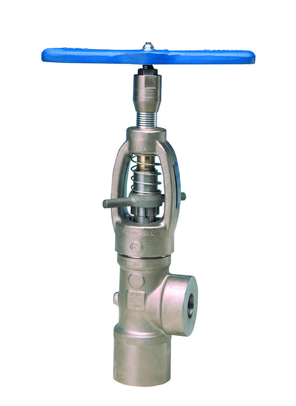
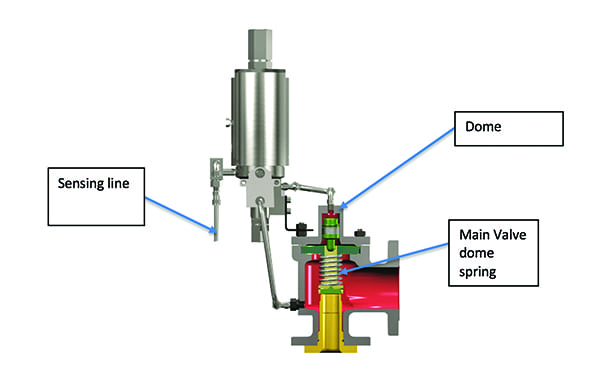
During plant commissioning, boilers are often filled at lower system pressures with the economizer experiencing conditions of about 1–2 barg (15–30 psig). The lack of sufficient operating pressure acting on the main-valve dome from the medium can lead to main-valve seat leakage and/or damage to the disc, seat bushing, and nozzle. Figure 1 demonstrates a typical cross-sectional view of these internals to show the flow path from the sensing line to the pilot to the main-valve dome above the valve seat and disc.
 |
|
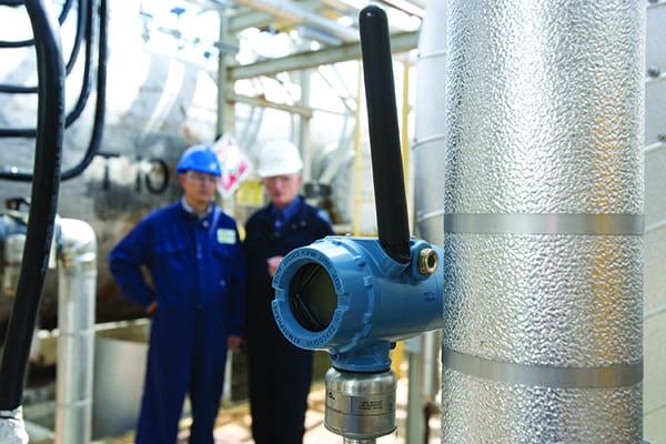
1. A typical pilot-operated safety valve is shown here with a sensing tube that passes the fluid to the pilot valve mounted on top of the main safety valve. Courtesy: Baker Hughes |
To ensure seat tightness, operators should install an auxiliary pressure source, such as a nitrogen bottle, to the POSV field test connection port to keep the main valve pressurized and closed during periods of low system operating pressure. By attaching an auxiliary pressure, regulated between 75% and 97% of set pressure, the main-valve dome may be pre-loaded with enough pressure to ensure sufficient closing force is provided to keep the main valve closed and leak tight. Another possible solution is to consult with the valve manufacturer to install an additional low-resistance spring in the main-valve dome designed to provide a downward closing force on the main-valve disc, which can work in conjunction with pressure in the main-valve dome during this low-pressure startup condition.
Another common failure mode is clogging of filter elements in the pilot sensing line from system debris that wasn’t completely flushed during commissioning. Clogging of a filter in the sensing line prevents pressure from reaching the pilot, resulting in reduced pressure in the main-valve dome. The reduced main-valve dome pressure causes the valve to leak and/or open, wasting steam, reducing efficiency, and causing startup interruption.
A proactive schedule for preventative maintenance on the pilot-valve filters during the first year of plant operation is highly recommended. Changing the filter element rather than cleaning it is typically recommended, as magnetite can be permanently embedded within the filter and cannot be removed by cleaning. Another option is to specify dual filters when purchasing the POSV from the valve manufacturer. This option reduces downtime as it allows for one filter to be serviced while the valve remains in operation simply by switching over to the backup filter. Under any scenario, a preventative maintenance schedule is always recommended, even with a dual-filter option.
As CCPPs today are transforming to peaker units and are demanded to reduce time to full power generation loads, operators are pushing ramp rates more aggressively than ever before. As the gas turbine engages, the exhaust temperature increase causes water in the economizer to expand, resulting in a rapid increase in pressure inside the unit. Ramp rates as high as 20 bar/second (300 psi/second) have been experienced in many plants that are transforming and coming online today.
These ramp rates are hitting the valve with a surge of pressure—a hammer—that exceeds the ranges for which POSVs were designed. By design, a flow path restriction exists from the POSV inlet to the pilot-valve dome to manage an offsetting dome pressure, which inherently results in micro-seconds of time lag between the pressure increase within the pilot valve and the inlet pressure acting on the seat. Such rapid pressure rise can lead to chatter in the pilot valve itself, which then causes the main valve to chatter, resulting in damage to both the pilot and the main-valve components.
Similarly, pressure increases instantaneously in the economizer when the feed pump is turned on, causing rapid pressure spikes in the economizer. These rapid pressure spikes cause water hammer, which is a pressure surge caused when the water is in motion and is forced to stop or change direction suddenly. The momentum of the fluid abruptly stopping or changing direction creates a pressure wave that travels through the media within the pipe system, subjecting everything in that closed system to significant and damaging forces.
 |
|
2. A pressure snubber can be added to the pilot sensing line to dampen pressure in systems susceptible to surges. Courtesy: Baker Hughes |
The best solution to address the problems from a rapid pressure ramp-up is simply to reduce ramp rates as much as possible. Slowing from 20 bar/second down to 10 bar/second can drastically reduce the severity of the impact to the point where pressure damping features, such as a snubber, can withstand the effects of the hammer. Manufacturer installation of a pressure snubber in the pilot sensing line (Figure 2) can absorb the effects of water hammer in the piping system and dampen the pressure before entering the pilot valve. This solution allows a smooth and stable pressure communication from the pilot valve to the main valve, eliminating chatter in the pilot and main valve. It’s good practice to consult the POSV manufacturer during system design for its pressure ramp rate limits and recommendations for snubber installation, if necessary.
Code Changes and the Future of Economizer POSVs
The ASME BPVC Section I committee recognized the need for code changes on economizers to address these application challenges. Recent changes to the 2017 ASME BPVC Section I code now allow economizers to have liquid-certified valves sized at 10% accumulation for over-pressure protection. This change will allow direct spring-loaded liquid-certified safety relief valves to be used and dual-certified to meet both ASME Section I and Section VIII requirements. These changes bring valve capacity and performance requirements in line with what products pressure relief manufacturers can offer to meet this demanding application.
However, it’s important to keep in mind that spring-loaded valves are often not designed to meet the same pressure limits as pilot-operated valves due to spring design limitations. Therefore, based on the need for higher-pressure, larger-orifice valves on today’s designed HRSGs, POSVs may be the only product that can be offered by valve manufacturers for the higher-pressure economizer applications. ■
—Matt Byers is the Consolidated Valves product management leader with Baker Hughes, a GE company; and Hari Nair is director—Power Industry with Baker Hughes, a GE company.