Steam turbine rotors bend during operation, but the bearing and supports are designed to keep the static and dynamic forces under control. However, bending can cause impact between stationary and rotating parts—often cascading impacts. An operator of many utility-scale steam turbines shares its extensive field experience identifying the root cause of failures as well as successful solutions.
Rotor bending that results in premature failure of steam turbine blades and other internal components is one of the most serious problems experienced in power plant operations. The problems often reduce plant availability by limiting generation and increase plant operation and maintenance cost. Extreme rotor bending problems often involve interaction between the turbine’s rotor and stationary parts. Rotor bending may be caused by a variety of static and dynamic factors, many of which will be explored in this article.
We begin with mechanical factors related to the rotor, the largest rotating assembly in the turbine. Working from the inside out, we next look at rotor balance issues, followed by rotor and casing misalignment problems, and problems caused by the casing. The discussion is based on the authors’ experiences at the six-unit, 1,890-MW Ramin Power Plant, located in Ahwaz, Iran. The units were commissioned from 1980 through 1985.
Avoid Rotor Rubs
It almost goes without saying that rubbing in the labyrinths or diaphragms, caused by insufficient clearances, disrupts the end sealing of the rotor. This situation commonly occurs when the high-mass rotor at operating speed comes in contact with a stationary surface, typically caused by a too-small clearance between the labyrinth or diaphragm gland seals and the rotor. Secondarily, there may be a localized temperature increase at the point of contact, causing increased metal temperatures at the point of contact due to friction.
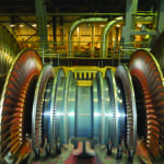
The forces produced by the impact of the large rotating rotor mass with the poorly functioning stationary seals often impress a layer of metal on the surface of the rotor. The rub can cause elastic deformation of the rotor at the point of impact and temporary rotor shaft bending. The shaft bending will usually cause increased vibration levels (Figure 1).
 |
| 1. Blade rubs cause bending. Rubbing in the sealing of a high-pressure rotor of a 300-MW unit caused bending of this rotor and blade tip rubs. Courtesy: Ahwaz Power Generation Management Co. |
Uneven cooling of the rotor, particularly after shutdown, also causes the rotor to contact stationary parts. After a unit shuts down, the relatively high-temperature rotor may bend solely due to the mass of the rotor and the distance between bearing supports, if left in a stationary position to cool. This situation can cause permanent shaft bending.
The effect of a permanent shaft bend caused by uneven cooling will immediately appear as high rotor vibration at the next startup. The vibration is caused by insufficient clearance between stationary and rotating parts, as well as a shaft located off-center in its bearing. Even if the clearance change is small, there may be significant rubbing along the rotor to cause damage. Again, the rubbing causes friction between stationary and rotating parts, localized heating of the rotor metal at the contact point, and shaft bending.
Furthermore, uneven shaft warming caused by rubbing between rotating and stationary parts can cause further bending of the shaft in the same direction of the existing bow and cause additional contact with stationary parts, increasing temperatures and therefore causing more bending. The effect cascades if allowed to continue. If the bending is allowed to continue, it is possible that the yield strength of the metal could be exceeded, causing a permanent deformation of the shaft. The allowed bending in 3,000-rpm turbines is up to 0.02–0.03 mm in each section. When on turning gearing, the limit is 0.05 mm.
To avoid rotor bending during cooling, turbine vendors provide very specific instructions on the allowable rate of cooling. For example, the turbine should remain on turning gear until the high-pressure (HP) cylinder temperature is below 150C and the oil temperature is below 75C. The turbine vendor also defines the rotational speed of the turning gear.
Prevent Rotor and Casing Misalignment
Misalignment of the coupling between two shafts or between a shaft and bearing may cause bending in the system. Misalignment between two shafts of an integrated rotor can cause an eccentricity of the mass center of the rotor, and this eccentricity at high rotational speed will produce a centrifugal force in the radial direction, causing bending of the rotor. Misalignment between the axis of rotation and the axis of the shaft can also cause bending in the rotor. There are six primary factors that can cause misalignment.
A poor connection between the turbine casing and the bearing pads on the foundation frame is one cause. If a pad experiences increased friction or stops sliding during thermal expansion (usually during startup) in the axial direction, the result is a tipping torque on the casing. This torque can cause a misalignment between the casing and bearing surface, causing vibration in the forward end of the turbine, foundation frame surface support deformation, and bearing pad stall.
Also pay close attention to the foundation frame—including bolts, keys, and pads—so that free movement of the bearing surfaces is possible, particularly while undergoing startup and load changes. The extent of the longitudinal and lateral thermal expansion bore centers of the cylinders and pad travel should be recorded for future comparisons. This process should be part of routine maintenance equipment inspections.
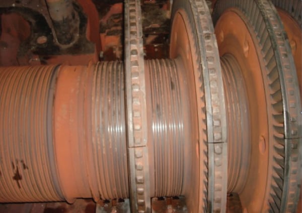
Another factor concerns the difficulty in assembling the HP turbine front bearing. While the shaft is rotating in its journal bearing, the shaft pushes oil from the bottom of the bearing, causing the oil film thickness to change. When this happens, the centerline of the shaft moves up and to one side. To account for this shaft movement, the segmented bearing should automatically adjust and the contact surface of the journal bearing will remain in a good position. If there is too much contact surface, friction will increase on the bearing surface, causing increased rubbing and corrosion of the bearing surface and increasing vibration and rotor eccentricity. The result will be bearing oil leakage and rubbing in the sealing glands. On the other hand, if the bearing contact area decreases, the oil film will cause uneven movement of the rotor within the segmented bearing, and the oil film will not form, also resulting in increased vibration (Figure 2).
 |
| 2. Shaft must stay centered. Relocation of shaft center in a segmented bearing while rotating can cause vibration. Courtesy: Ahwaz Power Generation Management Co. |
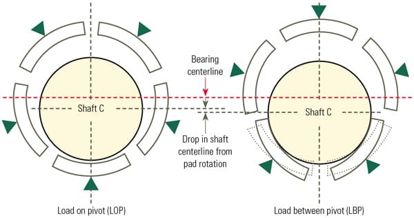
Don’t overlook the concentricity of the rotor with the bores and couplings. Correct rotor alignment is lost when the axis of one rotor is not continuous with the rotor in the following casing, in multi-casing steam turbines. The individually connected drivelines must operate as one long continuous, yet flexible driveline. After major steam turbine maintenance, it is important to confirm the alignment of the rotor to the couplings as well as any other factors that may cause change to the primary positions of individual casings, bearing, and rotors. During maintenance, if rubbing is observed at the end or intermediate sealing of the rotor or eccentricity of couplings, it is necessary to realign the driveline to avoid high turbine vibration, contact and rubbing of glands or labyrinth seals, and so on (Figure 3).
 |
| 3. Properly align the diaphragms. The diaphragms must be carefully aligned to the shaft centerline within the casing of this 315-MW turbine to avoid contact with the rotor blades. Courtesy: Ahwaz Power Generation Management Co. |
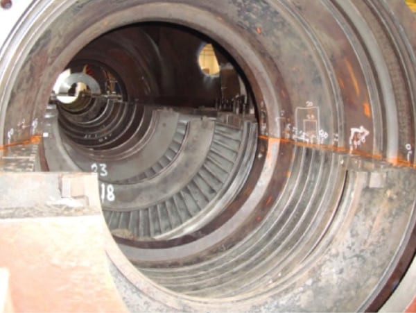
Remember that the axis from the center of the gland’s bore should coincide with the axis of the turbine rotor during normal temperatures experienced during turbine operation. Furthermore, it is essential to quickly identify any loss in sealing clearances during steam turbine warm-up. Changes in clearance may occur during warming that could cause bending of the cylinders due to differential temperatures between the upper and lower sections of the cylinder (Figure 4).
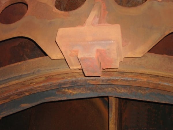 |
| 4. Precise alignment required. This photo shows the expansion key of the upper half of a low-pressure cylinder. Courtesy: Ahwaz Power Generation Management Co. |
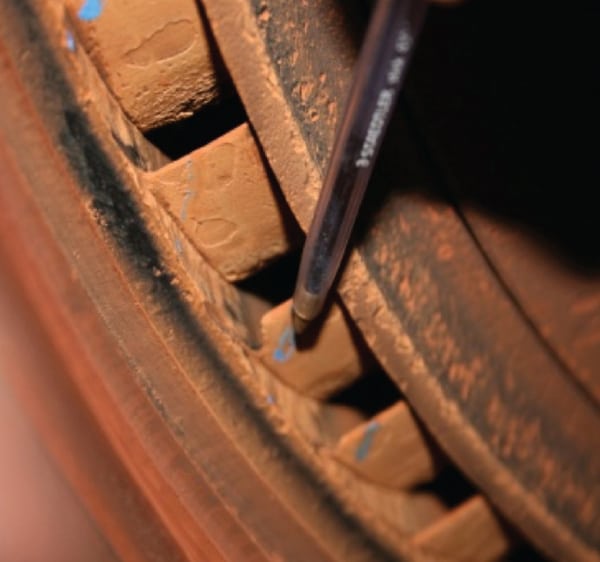
Finally, pay close attention to the possibility of contact rubbing of blade tips on the cylinder walls in reactive stages. Rubbing can cause increased vibration to blade bending, usually at the blade root (Figure 5).
 |
| 5. Avoid tenon extrusion rubs. This is an example of tenon extrusion in high-pressure rotor blades. Courtesy: Ahwaz Power Generation Management Co. |
Rotor Imbalance Increases Vibration
Shaft curvature also shifts the rotation axis of the shaft by moving the mass center of the rotor, creating vibration. This vibration affects blades in three significant ways.
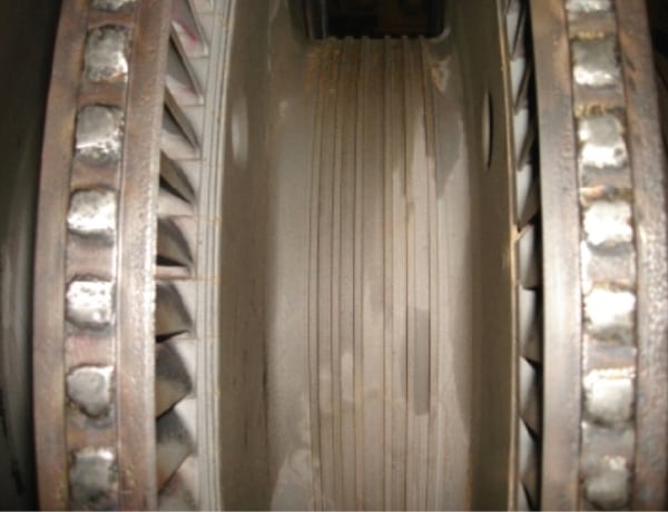
First, the vibration causes blade structural problems. The centrifugal forces encountered during operation are significant, causing an increase in the tensile forces in the blade cross-section and, if the center of mass is not on the radial line, bending stresses also occur. Additionally, bending stresses are created in blade joints under the pressure effects of the HP steam flowing axially through the turbine cylinder. The magnitude of these stresses is dependent on the flow rate of steam, the temperature drop across the blade stage, the rotational speed of the blades, and the blade weight. The temperature of the steam, superheated in the first stage and saturated in the final stages, will have an effect on the mechanical properties and corrosion of the blade materials (Figure 6).
 |
| 6. Corrosion causes imbalance. Failure of this high-pressure rotor control stage was caused by uneven distribution of steam due to corrosion. Courtesy: Ahwaz Power Generation Management Co. |
Second, blade vibration can be stimulated by external means, such as an unsatisfactory dynamic balance of the rotor, nonconformity of the diaphragm passages, deviation in the blade pitch, an improperly assembled joint between two half-diaphragms, or corrosion of the eternal edge of fixed blades.
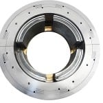
Third, the size of rotary blades and their method of installation on the rotors may be different. After a maintenance overhaul, the same weight and materials of all the blades must be carefully maintained, particularly when only a few blades are replaced. Even a small change in blade weight or center of gravity can cause a rotor imbalance and vibration (Figure 7).
 |
| 7. Failures can be caused by poor maintenance. This removal of the disk from the rotor was done incorrectly, causing deep scratches on the shaft. The repair will require rework and rebalancing of the shaft to prevent an imbalance that can cause vibration. Courtesy: Ahwaz Power Generation Management Co. |
 |
| 8. Steam can bypass bolts. Large bolts inserted into the holes are used to tightly secure the large horizontal joint flange in this high-pressure cylinder. The bolt holes are places where a steam jet leak can form due to cylinder deformation and changing duct pressures. Courtesy: Ahwaz Power Generation Management Co. |
Casing Also an Important Factor in Rotor Vibration
There are many ways that casing temperature fluctuations can cause steam turbine vibration. Casing problems can cause misalignment in many different ways, mostly related to expansion and contraction due to temperature fluctuations.
First, the turbine cylinder can have temperature stratification caused by insufficient thermal isolation from the casing and/or weak insulation in other areas. Loss of thermal isolation can be caused by poor insulation at connections between joints and pipes to the casings, usually at the bottom of the turbine. Poor casing insulation at the bottom, for example, can cause a temperature gradient from the top to the bottom of the casing, which can lead to casing distortion and elastic rotor bending. The vendor will define the acceptable casing temperature gradient. In our experience, the gradient must be no more than 60C. New HP turbines are particularly sensitive to casing thermal gradients.
Next, if the turbine is started from a hot condition before it has returned to within curvature limits, then rotating blades and stationary diaphragms may rub and cause damage to seals and diaphragm glands. As shaft weights increase, so do the dimensions of the turbine rotor, turbine cylinder, and the thermal inertia of the shaft. The effect is to require longer periods of time between startups (and on turning gear) so any curvature of the rotor is removed before the next startup.
The cylinder bending can be estimated with knowledge of its dimensions and materials of construction. Cylinder bending (mm) can be found by the expression α Δt L2/8D, where Δt is the temperature difference between the top and bottom of the cylinder (C), L is the cylinder length (mm), D is the external diameter of the shell averaged across its length (m), and α is the coefficient of linear thermal expansion, usually about 13.6 mm/mm-C, or any other consistent set of units. The amount of permitted cylinder bending is determined by the tightest tolerance between diaphragm and end glands. For example, if the HP cylinder dimensions are l = 3,620 mm and D = 1,840 mm, and the tightest tolerance of the diaphragm gland is 0.6 mm, the allowable temperature difference from the top to the bottom of the cylinder is 50C.
The effect of thermal bending of a rotor on the casing can also be determined. When the casing top is hotter than the bottom, the casing tends to bend down. If the temperature gradient is constant from the top of the casing to the bottom and along its length, then the maximum bending stress occurs mid-casing vertically and between the casing supports horizontally. The bending or deflection under these conditions can be determined as α Δt (L Z – Z2) x 103/2D, where L is the casing length between supports (m), Z is the distance from front casing support to location of interest (m), and the other variables remain as defined above. Assuming the midpoint of the casing length is used, L/2 can replace Z to find the maximum deflection.
The temperature gradient along the blades and diaphragms must also be considered during a hot start. In a hot turbine startup, if the steam is relatively cool, then the diaphragm and blade metal temperatures will be cooler than the rotor. In that case the diameter of the diaphragm holes will increase more rapidly than the rotor diameter, producing radial looseness and decreasing blade and diaphragm clearances. Using a typical coefficient of linear thermal expansion, a diaphragm sealing diameter of 500 mm will increase 0.3 mm for every 100C temperature difference between the rotor and diaphragm.
So, if a rotor has a higher curvature than the normal range and if steam flow path regulation has not been done carefully during a hot startup, rubbing should be expected.
Calculations using these formulas and application experience tell us that the temperature difference between the top and bottom of the HP cylinder shouldn’t get higher than a defined normal limit during steam turbine startup. If that temperature difference limit is exceeded, radial distances in the front end gland will decrease considerably, causing rubbing, followed by rotor bending near the control stage.
The experience of many steam turbine repair companies is that the reason for the HP cylinder’s bending is condensation of steam within the hot turbine cylinder when stopped. High-temperature heat transfer to vaporize this condensate cools the bottom of the cylinder while the top of the cylinder remains relatively hot. As a result, the cylinder will bend down while the top of the casing will remain straight, in most cases.
Also, poor clearances in the low-pressure (LP) and intermediate-pressure (IP) cylinder frames in multi-cylinder turbines can occur when the distance bolts and washers are incorrectly installed. Distance bolts are used to secure the LP and IP casing frames to the foundation. At the time of operation and nominal load, if condenser pressure (vacuum) and condensate temperature are within normal range, then the clearance should be as designed. But if the condenser pressure (vacuum) is abnormal and condensate temperature is high, then the LP cylinder gets hotter than the allowed limit, causing more volume expansion in the condenser. The result is that the distance bolt clearance is decreased or goes to zero. If design clearances aren’t observed, turbine vibration may increase and the turbine load must be reduced.
Next, don’t forget the bolts, pins, and other casing joints. Casings for HP turbines have thick walls, as well as big horizontal joint flanges that require bolts and pins. There are times when turbine loads quickly change or the casing flange and walls are heated unevenly during startup or shutdown of a unit. A temperature difference between the top and bottom of the HP and IP casings (usually 50C to 70C) and flange pins (maximum 15C to 25C) can cause steam leakage through the casing horizontal joint.
Finally, uncompensated movement of steam pipes connected to the casing can cause casing movements and rotor vibration. This is particularly true for large-diameter pipes with thick walls. When the turbine is operating, the rotor has axial movement, as does the turbine casing. Thermal expansion of the system is accounted for in the turbine design. The forces and moments that these large pipes apply to the casing are also considered during turbine design. Excessive pipe connection loads may cause casing deformation, and the bending moments applied to the casing flanges may also cause displacement and movement of the cylinder within the casing, either of which can increase rotor vibration.
— Farshad Shamoradi (fshamoradi@yahoo.com) is manager of the instrument department, Naser Mohammadi is manager of the engineering department, and Mahdi Heidari Kahkesh is manager of overall maintenance at the Ramin Power Plant, Ahwaz Power Generation Management Co.