Attemperation equipment is necessary to control steam temperatures at many power plants. However, when the equipment functions improperly or the design is flawed, thermal quenching/shock can damage piping. Proper inspections and sound engineering evaluations can identify problems, allowing corrections to be implemented before failure occurs.
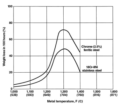
Most large combined cycle power plants are equipped with steam attemperation equipment to control temperatures below design limits during normal operation and anticipated transient conditions. For power stations with reheat systems, design requirements place spray valves in the heat recovery steam generator (HRSG) high-pressure (HP) and reheat (RH) interstage piping and in turbine bypasses to cold RH and condenser. High-temperature piping exposed to spray water, commonly grade 91 or 22, have experienced the damaging effects of thermal quenching/shock resulting from direct contact between liquid water and hot metal surfaces, the consequent development of skin cracking (also sometimes called “craze” cracking), and after prolonged exposure, leaks and failures.
Three case studies will be presented in this article describing the engineering evaluation of service-induced cracks to support the scheduling of pipe replacements; the design of efficient nondestructive testing (NDT) inspection plans, in accordance with the American Society of Mechanical Engineers (ASME) B31.1 “Power Piping” code Chapter VII guidance; and issues with spray control during transient operation.
Engineering Evaluation
A 625-MW power station with more than 15 years of commercial operation experienced craze cracking in 2015. This natural gas-powered combined cycle plant has two three-pressure HRSGs with RH capability and supplemental firing. Each HRSG is equipped with HP superheater (SH) and RH systems that consist of two sets of assemblies connected by external interconnecting piping, which contains the attemperator valves for steam temperature control. The mechanical details for both are SA-335-P22, seamless 16-inch outer diameter, with 3-inch (HP SH) and 0.843-inch (RH) wall thickness.
 |
|
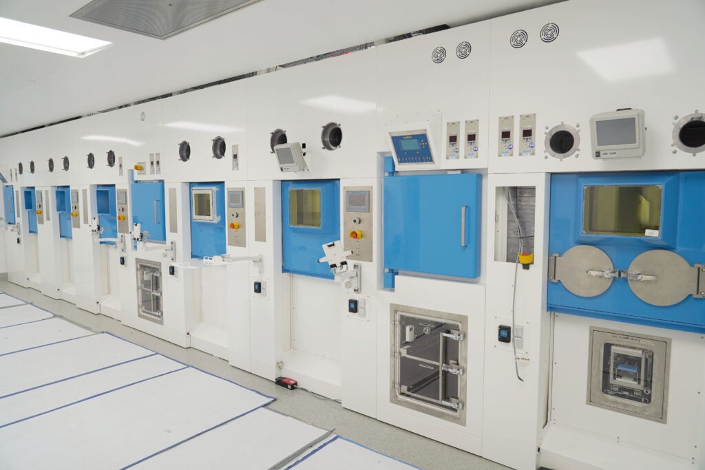
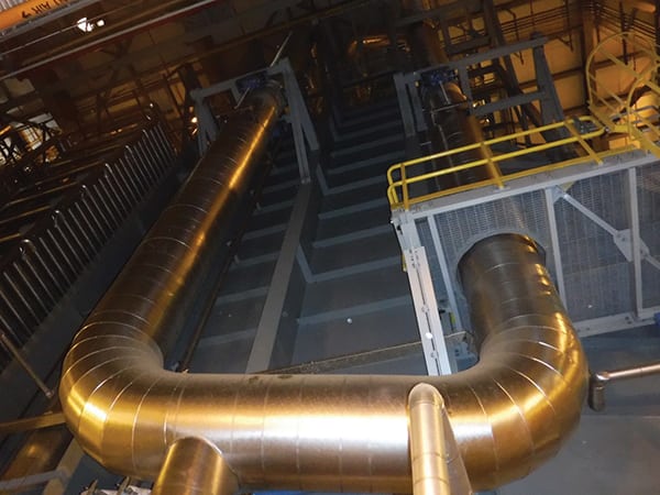
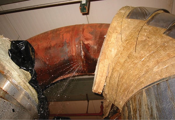
1. Nondestructive testing utilizing the ultrasonic linear phased array method was conducted on the high-pressure superheater and reheat interconnecting piping shown here. It found cracks and crack-like indications that required action. Courtesy: Tetra Engineering Group Inc. |
A site visit characterized the condition of the piping and determined the HP SH and RH sections were not fit for continued operation. The onsite inspection, performed by American Society for Nondestructive Testing (ASNT)-certified NDT technicians experienced in ultrasonic linear phased array (UT LPA) testing, found several cracks and crack-like indications that represented an impediment for long-term operation. For that particular inspection, UT LPA with an Olympus flaw detector proved to be an efficient method for detecting all shock-related indications at the inner surface of the pipe and embedded in the pipe wall. Figure 1 shows the preparation process for two damaged pipes. Note the areas of interest has no insulation and the outer surface is properly cleaned. All collected data, as part of a more in-depth analysis, served to create the necessary baseline for the API 579/ASME FFS-1 Fitness-for-Service.
 |
|
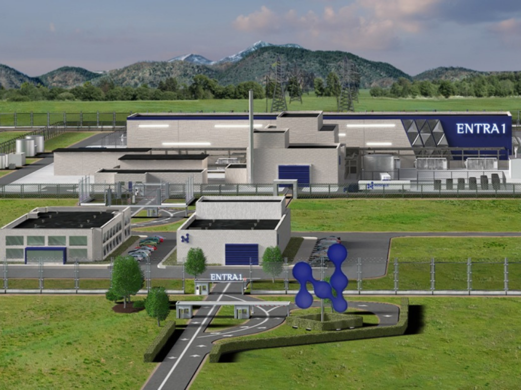
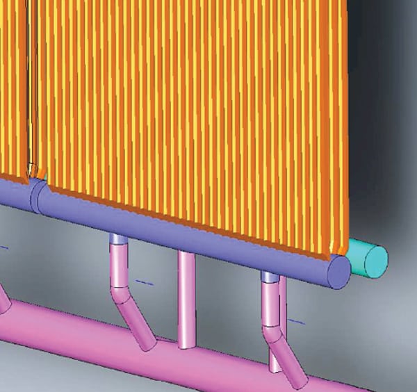
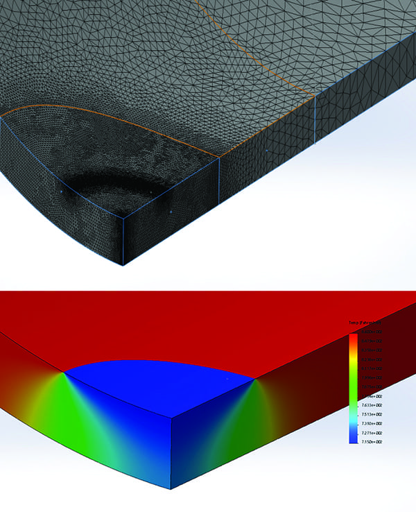
2. The top image shows the mesh used in SolidWorks simulation to complete the fitness-for-service evaluation. A finer mesh allows for more accurate results around the thermal affected region. The bottom image shows the solution obtained from the thermal simulation. Courtesy: Tetra Engineering Group Inc. |
An API 579/ASME FFS-1 Fitness-for-Service evaluation was applied to estimate the remaining cycles to failure. The analysis integrated field data from the UT LPA, operating data, mechanical design specifications, and in-house engineering methods to reach an estimate of the remaining reliable life. Figure 2 shows the analysis and procedure followed using the SolidWorks finite element software.
The first step was to prepare a finite element model and run an analysis that addressed all boundary conditions, fixtures, and external loads applied to the pipe model. Next, a mesh was generated with an emphasis on the affected zone where thermal quench results. The program solved the simulation and generated the expected stress and temperature values needed to support the engineering calculations of remaining reliable lifetime.
Preliminary results concluded that one of the HP SH pipes required replacement before reaching a maximum of 50 cycles. The remaining RH and HP SH sections were evaluated to be capable of at least 100 cycles before being decommissioned. It was assumed, based on experience, that the plant would cycle once a day.
In another evaluation, a four-unit station suffered moderate bulging at the bottom of three RH bypass piping sections near the desuperheater sprays in 2009. Two years prior, the same components experienced distortion and cracking near the pressure reduction valve area. An NDT inspection determined the new incident caused no cracks on the surface.
This power plant was built with three identical units equipped with one Siemens-Westinghouse 501FD Econopac gas turbine each and designed as triple pressure reheat HRSGs capable of providing steam to one Alstom steam turbine as a 3x3x1 configuration. The RH bypass piping has an outside diameter of 30 inches and a wall thickness of 0.39 inches.
Part 8 of the FFS-1 Standard (2007 version) was applied to determine if the pipe deformation was critical. This section of the code covers fitness-for-service assessment for pressurized components with weld misalignment and shell distortion, including out-of-roundness and bulges. For bulges, Level 1 and Level 3 are the only options for evaluation. Level 1 is based on fabrication tolerances of the original construction code (ASME B31.1). If the geometry of the affected component is within the established tolerance, then it is satisfied. Level 1 found two of the three pipes did not meet the standard. This forced a more detailed evaluation—a Level 3 assessment. Final calculations determined the bulges were significant stress risers causing stresses to be above yield. Consequently, replacement of the damaged sections was recommended.
These inspections and engineering evaluations of the damage, which is characterized by NDT, have proved to be of great importance in assessing the extent of damage, expected remaining reliable lifetime, and determining the schedule for material replacements. Fitness-for-service methods have proven valuable in establishing a consistent framework for evaluating thermal quench damage and its progression.
NDT Inspection Plans
For decades, industry leaders have worked to help plant owners/operators understand the origins of thermal quench damage and formulate steps to improve the reliability of these piping systems. This issue has become a significant concern especially for plants that operate in daily cycling at low load and “low-low” load. Partly in response to an initiative by the ASME code Section B31.1 Chapter VII Operations and Maintenance requirements 10 years ago, today maintenance managers can implement effective inspection programs to identify damage, and prioritize needed repairs and, in some cases, pipe replacements.
A robust program, unique to every plant, will take into consideration the number of bypasses and location of all valves, pipe layout, pipe and adjacent weld material, adequate inspection methods, and frequency. Also, in accordance with the latest guidance, a record of the inspection locations, inspection results, and any corrective actions should be maintained by the plant to facilitate future inspection planning and the potential for fitness-for-service evaluations should damage be identified which is not immediately repaired. This plan should be assembled by experienced plant personnel or by a third-party firm with similar capabilities.
For a power station comprised of two three-pressure HRSGs with RH, an inspection scope that covers each unit’s bypass and interstage piping is paramount. Typically, this includes the first field weld upstream of the bypass valve as well as the first field/girth weld downstream of the bypass. There are instances where multiple field girth welds are closely downstream of the valve if repairs have required replacement of sections of piping.
To conduct the inspection, insulation must be removed at least three pipe diameters downstream from each spray injection location. Also, some locations might require scaffold to be built, if access is limited. Girth welds should be inspected by UT LPA or volumetric shear wave for crack detection using calibrated NDT hardware and performed by a certified NDT inspector. Wet fluorescent magnetic particle testing (WFMT) is an acceptable alternative, if UT LPA is not available or if other constraints prevent its application. Proper surface preparation is essential for UT transducer application and accurate results.
Spray Control Issues
Adequate spray logic contributes greatly to temperature regulation and thermal quench prevention. Attemperator issues are known to cause excessive spray release that translates into unabsorbed liquid capable of damaging the inner surface of pipes. The most reliable solutions include improving spray control, installing advanced spray valve designs, changing the attemperator piping layout and upgrading capabilities, and increasing drain capacity. These methods have all provided the potential for improved reliability and extended service life.
In 2005, a power plant with three three-pressure HRSGs reported excessive spray at inappropriate times and excessive cycling of block valves during operation. The attemperators belong to the RH interconnecting piping adjacent to the boiler. A preliminary diagnostic determined the original logic inhibited an open signal to the block valve when the feed pumps were not running by blocking spray flow demand signals. When both feed pumps were running, spray flow demand signs were allowed to pass. When spray flow demand signals were greater than 3%, an open signal was generated. If spray flow demand dropped below 3% for more than 60 seconds, the block valve was closed. To correct the anomaly, the block valve open signal was modified.
Upgrading or replacing desuperheater sprays also prevent future damage to valves and inadequate spray evaporation. A proper analysis should focus on general attributes and deficiencies that a current design and potential replacements have for a particular plant. This requires reviewing two or more available designs and directly comparing them with existing HRSG desuperheaters. Also, it should take into consideration piping and spray layout, thermal performance under full load or part load operation, and potential for vibration and cracking. Simulation programs such as PowerPlantSimulator&Designer—a KED GmbH product—are capable of reproducing anticipated system responses. Plant owners and managers must balance, as always, the cost of major attemperator system upgrades with other budgeted activities.
Inspection Programs Work
A significant reduction in critical equipment damage is possible with adequate programs that follow ASME B31.1 Chapter VII guidelines and evaluate detected degradation using the ASME FFS-1 procedures. Current practices have proved sufficient to safeguard energy assets worldwide during normal operation and transient conditions.
To monitor and prevent thermal quench damage effectively, asset owners need to implement a covered piping systems program that includes efficient NDT inspection plans. If service-induced cracks are present due to spray control issues, an engineering evaluation and attemperator spray upgrade must be considered. ■
—Robert Rosario, PE is senior engineer with Tetra Engineering Group Inc. in Weatogue, Connecticut.