How leaking valves drain profits
INFORMATION TECHNOLOGY
How leaking valves drain profits
Identifying and then repairing leaky steam- and water-cycle isolation valves is a quick and cost-effective way to improve plant efficiency. Despite the obvious opportunities for recovering lost generation and reducing fuel costs that it affords, this performance-improvement technique doesn’t get the attention it deserves. Although pinpointing leaks is tedious work, a program for doing so provides an immediate and ongoing return on investment.
Automating leak detection makes the process easier and foolproof, and it ensures that a plant is running at peak profitability at all times. For example, computerized performance monitoring systems detect leaks indirectly by noting the losses in efficiency they cause. In January 2004, Ameren Corp. installed EtaPRO performance monitoring systems from General Physics Corp. (Elkridge, Md.) on its large thermal generating units to provide real-time performance information to plant personnel and corporate management. Later that year, one of these systems proved invaluable in the diagnosis of an efficiency problem. The following case study describes how.
Elevated heat rate
In December 2004, routine reviews of daily performance reports for one of the Ameren units revealed that actual turbine-cycle heat rate (TCHR) was significantly higher than expected values at loads above 350 MW. To discount the effect of unit loading, TCHR and net unit heat rate (NUHR) were trended for four weeks. The results then were filtered to reflect only those periods when the unit was operating at full load and under steady-state conditions (Figure 5).
5. Trend-spotting. Net unit heat rate (actual) at full load (595 MW) and at steady-state operation.
Courtesy: General Physics Corp.
Because the degradation in heat-rate performance occurred over a relatively short period of time, leaking cycle isolation valves were the obvious suspects. Plant support personnel were asked to develop a high-level cycle isolation program for the affected unit. They began by retrieving the unit’s turbine-cycle piping and instrumentation drawings and identifying and highlighting the key valves on them.
A survey of isolation valves
Next, attention was focused on low-point drain valves on main, reheat, and extraction steam lines, on main turbine and boiler feed pump turbine drain valves, and on gland sealing steam valves. The result of these reviews was a checklist of about 50 valves deemed worthy of inspection as part of a unitwide survey.
To prepare for the survey, plant dispatch, operations, and plant support personnel were informed of the procedure and its schedule. The unit was stabilized at roughly 572 MW (net) with the controls in turbine-follow mode and the boiler master in automatic. Boiler sootblowing was suspended for the duration of the survey.
Each valve on the list was unlocked (if necessary) and closed and tagged by operations personnel; the closure time was noted by the survey coordinator. All manual low-point drain valves were closed by hand until seated and then cracked open one-half to three-quarters turn to ensure that no condensate would form in the steam line during the duration of the survey. Plant support personnel checked each valve for any indication of leakage before and after its closure.
The valves on the checklist were observed locally for leakage using several methods, including ultrasonic leak detection, temperature measurement, and/or audible signs. Plant support personnel operated the ultrasonic detectors and temperature measurement equipment. The survey coordinator noted any local field indication of leakage and estimated its magnitude.
Concurrently, plant support personnel in radio contact with the survey coordinator used the recently installed EtaPRO performance monitoring system to measure—in real time—the unit’s turbine-cycle heat rate. They noted any detectable deviations in this heat rate resulting from closure or isolation of a particular valve.
After all valves were closed, the unit was left alone for a 2-hour period. At that time, all valves were returned to their normal operating position and survey tags were removed. It took about 8 hours to complete the entire cycle isolation valve survey.
Three leaks were stealing 120 Btu/kWh
The survey indicated that three valves had major leaks. Two were associated with the gland steam sealing system, and the third was an automatic drain valve for the main steam leads.
The first two valves were the air-operated steam seal feed valve (SSFV) and the seal feed valve bypass. Upon further inspection, the survey team found the SSFV partially open, so operators closed it completely from the control room. The result of this action was an observed decrease (improvement) in gross turbine-cycle heat rate of about 30 Btu/kWh.
The steam seal feed valve bypass also was found to be partially open. At the request of the survey coordinator, operations personnel completely closed it, too, again producing an observed decrease in gross turbine-cycle heat rate—in this case, 20 Btu/kWh.
The third leaking valve was a motor-operated automatic drain valve (called the main stop, or MS, auto-drain valve) below the seat drain. This valve is open during unit start-up and closed during normal operation. It was found to be one full turn off of its seat, allowing main steam to bypass the turbine and flow to the condenser. After this valve was completely on December 17, 2004, gross turbine-cycle heat rate was observed to decrease by about 70 Btu/kWh (Figure 6).
6. Recovered revenue. The effect of fully closing three leaking valves on gross turbine-cycle heat rate.
Source: General Physics Corp.
How performance monitoring helped
The unit’s EtaPRO performance monitoring system calculated gross turbine-cycle heat rate by dividing the heat input to the turbine cycle (in Btu/hr) by gross generation (in kW). The calculated heat rate depends on the rates of flow and enthalpies of steam and water into and out of the turbine. EtaPRO bases its calculations of these two values on measured temperature and pressures, as well as on energy balances (where necessary).
Plant personnel used another tool to validate the data collected during the survey: General Physics’ Virtual Plant, a first-principles, integrated boiler and turbine-cycle model. During the survey, engineers modified the thermodynamic model of the unit to account for the leakage from the three partially open valves (Figure 7).
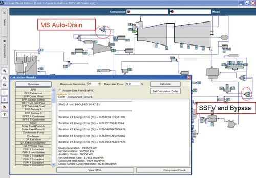
7. Hurting heat rate. The Virtual Plant model was modified to take into account the leakage from SSFV, SSFV Bypass, and MS Auto-Drain.
Courtesy: General Physics Corp.
When the MS auto-drain valve was closed, the model reflected a 77 Btu/kWh decrease in TCHR, which correlates well with the 70 Btu/kWh decrease observed by EtaPRO. Similarly, when the gland steam sealing system valves were closed, the model reflected a 41 Btu/kWh decrease in TCHR, which correlates well with the observed 50 Btu/kWh decrease.
The cumulative effect of the three leaking valves was an increase of 120 Btu/kWh in gross turbine-cycle heat rate, which corresponded to an increase of 150 Btu/kWh in unit heat rate. Ameren estimated that this increase raised the unit’s annual fuel cost by $760,000 and resulted in lost generation of 24,500 MWh.
Following this survey, a more-thorough survey by an independent third party validated the preliminary findings. Repairs were made to the three leaking valves and/or their actuators during a routine scheduled overhaul of the unit in the spring of 2005.
—Case study provided by J. Bitner and G. Noë of General Physics Corp. and M.Kloog and J. Magallanes of Ameren Corp.