Evolving environmental regulations have forced many coal power plant operators to re-evaluate how they handle water and ash. Many units have been retrofit with dry handling systems, but there are other acceptable alternatives. A facility in the southern U.S., for example, successfully installed a combination bottom ash dewatering and transport water clarifying system with remotely located submerged flight conveyors and circular clarifiers with internal rake mechanisms to meet its needs.
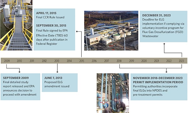
Numerous utilities have moved forward with projects that address new groundwater and surface water regulatory requirements, with attention to bottom ash transport water and bottom ash impoundment closure. A main driver of these projects was the implementation of the U.S. Environmental Protection Agency’s (EPA’s) Coal Combustion Residuals rule and Effluent Limitations Guidelines (ELG).
To date, about half of the U.S. coal fleet has converted their traditional wet bottom ash systems to either dry handling systems or closed-loop recirculation systems. United Conveyor Corp. (UCC) has been contracted to provide wet-to-dry ash conversions, and wastewater management and treatment technologies on 53 plants, covering 114 operating units. What it’s found is one size does not fit all. Thus, each plant must be evaluated based on its own set of operating parameters, physical conditions, and design criteria, allowing a sound technological solution to be applied.
Evaluating the Situation and Identifying Objectives
A utility in the southern U.S. was faced with the challenge of converting a wet bottom ash sluice conveying system that covered multiple operating units. The existing system combined conveying lines from multiple operating units into two sluice lines that directed the bottom ash slurry to a receiving pond. In between sluice conveying cycles, the bottom ash was excavated from the pond and allowed to dewater prior to transport to a dry landfill facility.
Given the complexity of the multi-unit sluice system and associated water balance, coupled with some uncertainty relative to legal challenges and possible modifications to the ELG, the utility wanted to implement a technical solution that afforded it maximum operating flexibility for current regulatory requirements and potential future revisions. The technology options were reviewed relative to a broad list of design criteria, which included budget, plant water balance considerations, outage requirements, ash conveyor capacities, physical parameters, conveying distance considerations, site environmental and wastewater management considerations, operations and maintenance issues, ash characteristics, multiple unit synergies, ash marketability and beneficial reuse desires, and unburned carbon concerns. Particular emphasis was placed on available budget and desired performance requirements.
The project required the new bottom ash dewatering and wastewater treatment technologies to meet the following criteria:
- ■ Dewater bottom ash to approximately 15% to 20% moisture. (The target was generally based on Paint Filter Test requirements—an EPA-approved compliance test method—and ensured sufficient moisture to limit potential fugitive dust emissions and optimal landfill compaction.)
- ■ Receive and process 2,700 gallons per minute (gpm) under typical conditions with maximum flow of 5,400 gpm.
- ■ Achieve 30 ppm total suspended solids (TSS) on a 30-day rolling average and 100 ppm daily maximum TSS.
- ■ Maintain a pH between 6 and 9.
- ■ Utilize existing sluice pumps for conveying from the bottom ash hoppers.
- ■ Meet current discharge requirements. (This assumed the final ELG would allow discharge of bottom ash transport water, which is subject to ongoing EPA review with expected confirmation in 2019.)
- ■ Be capable of conversion to a closed-loop, zero-liquid-discharge system with water quality suitable for feeding existing high-pressure, clean-water sluice pumps.
- ■ Produce water quality that would allow for potential reuse as makeup in the plant’s wet flue gas desulfurization (FGD) operations.
A Novel Ash Dewatering and Water Clarifying System
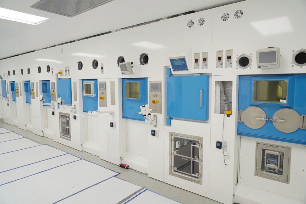
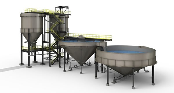
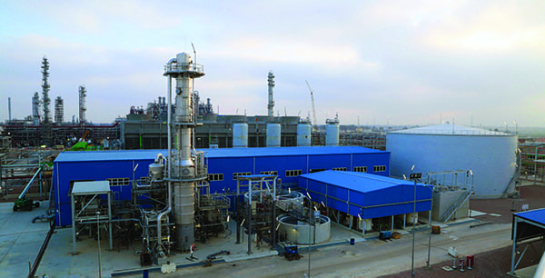
After evaluating several dry conversion options, including traditional dewatering and dry-handling technologies, the utility selected a combination bottom ash dewatering and transport water clarifying system with remotely located submerged flight conveyors (R-SFC) and circular clarifiers with internal rake mechanisms. The selected system included two processing trains, one primary and one fully redundant standby, that could receive the bottom ash slurry (ash and transport water) from the two operational conveying lines with crossover capabilities to either process train (Figure 1).
|
1. The system shown here includes bottom ash dewatering and transport water clarifying equipment with remotely located submerged flight conveyors and circular clarifiers with internal rake mechanisms. Courtesy: United Conveyor Corp. (UCC) |
A primary consideration in this technology selection was the cost benefit of a system with multiple-unit synergies, whereby more than three operating units could be directed to this fully redundant system without modifications within the powerhouse and under each operating unit. Schedule flexibility and reduced installation costs were realized as all construction activities could be executed in a remote location and without the need for a planned outage.
The first phase of the system featured the patented technology known as the Continuous Dewatering Recirculation (CDR) system with Integral Coal Combustion Residual High Flow Plate Separator, which is being used widely throughout the U.S. coal fleet for the management of bottom ash dewatering and bottom ash transport water treatment.
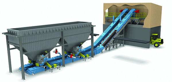
In this first phase, the bottom ash sluice lines are directed into the R-SFC where the flow enters a baffle-ring assembly that impacts on abrasion-resistant receiving plates to dissipate the energy and force the large, coarse particulate to readily drop out of suspension. Collected solids are transported via a dual-chain scraper operation along the bottom of the R-SFC, up an inclined dewatering ramp, before discharging into a dry, three-walled concrete bunker.
The partly clarified water is then directed under a series of chambers where the water moves upward through narrowly spaced lamella plates. As the water flows in between each pair of plates, the particulate with a specific gravity greater than water will settle onto the top surface of each lower plate. Once settled onto the lower plate, the particles will sheer off the surface of the plates and settle out in the lower section of the R-SFC.
The enhanced settling performance of the lamella plate design provides the following benefits on system performance:
■ Reduced solids carryover to the clarifier, thus maximizing its settling efficiency.
- ■ Reduced flocculent consumption to remove fine particulate in the secondary system phase (clarifier).
- ■ Reduced or eliminated particle neutralizing coagulant to enhance fine particulate settling performance in the secondary phase (clarifier).
The clean water then continues to travel upward and exits at the top of the lamella plates where it is directed to a series of internal troughs that ultimately exit the R-SFC and overflow into the secondary phase of the system—the clarifier.
The UCC clarifier design approach is largely based on client-specified construction materials, UCC laboratory testing, analysis of representative samples, and the target TSS outlet concentrations. Material samples (such as bottom ash and economizer ash) are tested for particle size distribution and specific gravity. Settling velocities are determined mathematically and through experimental testing to properly size the R-SFC lamellas and the clarifier. A detailed study is conducted to achieve a clear water overflow from the top of the clarifier, while preventing undue compaction of agglomerated solids in the clarifier bottom, therefore mitigating the risk of plugging the slurry outlet and/or tripping the internal rake drive unit.
For an additional level of clarification, the system also includes chemical injection skids that introduce flocculent for fine-particle agglomeration and enhanced settling. This polymer is injected into the drain piping between the R-SFC and the clarifier and then fully mixed with the water in the clarifier center feed well. As particulate settles in the clarifier, the agglomerated solids are directed via a low-velocity raking mechanism to the discharge outlet at the bottom center of the clarifier.
The outlet size and associated piping is uniquely engineered to remove the slurry at a reduced velocity that does not upset the agglomerated solids (that is, limits the breaking of flocculent bonds). Pump sizes and pipe diameters are specifically selected to reduce the risk of plugging the slurry lines. The slurry is then pumped from the clarifier outlet to the idle R-SFC, where it is added to the coarse bottom ash and then conveyed up the dewatering ramp and discharged into the dry concrete bunker for final transport to a landfill.
Proven Results
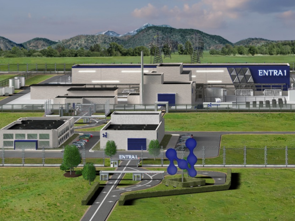
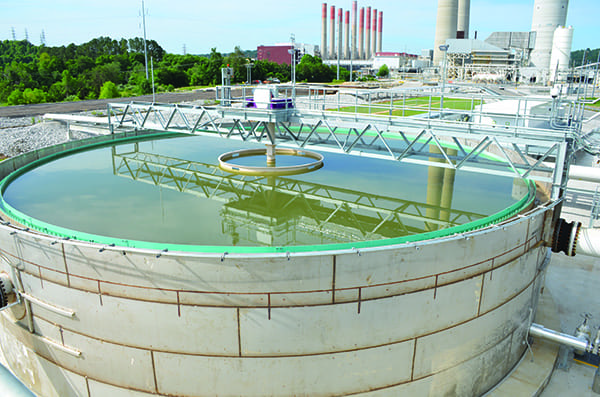
The R-SFC and clarifier system (Figure 2) has met all performance guarantees through an extended period of operation, including periods of varying fuel types and boiler loads. In particular, the effluent water quality has consistently remained well below the daily maximum and monthly average TSS target. In addition, the discharge water has remained slightly basic with a pH range of 7.5 to 8.5 with an average of 8.0.
 |
|
2. Clarifiers are used in many wastewater treatment applications. Their purpose is to slow the movement of water so the force of gravity can separate suspended particles. Courtesy: UCC |
The system also has shown favorable performance on total dissolved solids (TDS) concentrations, with the clarifier system showing no influence on inlet constituent levels, and in at least one case, reducing TDS levels from 146 milligrams/liter (mg/L) at the inlet to 110 mg/L at the outlet. As a once-through system, this performance was expected relative to minimizing the amount of time the bottom ash particulate and clarifier slurry remains in contact with the transport water.
By design, the solids collected in the system are intended to remain in contact with water for no more than 24 hours, and typically less than 12 hours for most of the material. This reduces the risk of solids dissolution into the transport water. If the system is modified to operate as a fulltime closed-loop, zero-liquid-discharge system, TDS levels would need to be monitored on a consistent basis for cycling up of constituent concentrations.
The successful implementation of the combined bottom ash dewatering and transport water clarifying system utilizing R-SFCs and clarifiers is a proven case study of state-of-the-art technologies that can readily meet new and pending regulatory requirements while providing for expanded operating flexibility. In particular, the system has produced an effluent water quality that is suitable for discharge under current permit requirements, can be readily recirculated in a closed-loop, zero-liquid-discharge system with utilization of existing pumps, or can be utilized for FGD makeup and process water. ■
—Kevin McDonough is vice president of sales and marketing with United Conveyor Corp. (unitedconveyor.com).