Accurate knowledge of the water level in any boiler drum application is an absolute necessity. While operating a boiler with low water level is one of the leading causes of boiler failure, operating with a high water level may produce less-than-optimal steam, as well as damage to the steam turbine by moisture carryover. Understanding the ASME Boiler and Pressure Vessel Code (Code) requirements is vital for employee protection and safe equipment operation in your plant.
The Code is a key resource for those specifying, installing, maintaining, and operating power boiler instrumentation, such as the various types of level instrumentation installed on your boiler drum. Understanding the different types of level instrumentation available for drum level measurement may help prevent serious consequences caused by incorrect or underrated selections. The primary focus of this article is Sections 1 and 7 of the Code.
What the Code Requires
The general requirements for level instrumentation used on power boilers are defined in Section 1 of the Code:
- Minimum number of level instruments required for direct reading gauge glasses.
- Remote (indirect) level transmitters for observing the level from the control area.
- Placement of the indication range for an instrument when installed on the drum.
- Minimum pipe size requirements for vessel and drain connections.
- Valve requirements, characteristics, and installation requirements.
- Information about material and design limitations.
The minimum Code requirement for water gauge glasses is use of at least one gauge glass that is in service at all times for applications operating up to 400 psi. For applications with a maximum allowable working pressure above 400 psi, one of the following combinations must be in place:
- Two gauge glasses in continuous service and visible by the operator.
- Two independent remote indication systems continuously displayed to the operator combined with a single gauge glass, which may be isolated but must be maintained in serviceable condition.
- One independent remote indication system combined with one gauge glass (in service at all times). Both of these instruments must be continuously displayed to the operator. A camera and display for a remote image of the gauge glass is considered acceptable, but two separate means of indication are required.
There are four types of water gauge glasses: tubular, reflex, flat glass, and ported. Tubular glass offers the least safety because it uses thin glass and is limited to 250 psi. Reflex glass (also known as prismatic glass) can be used up to 350 psi. Flat glass (also known as transparent glass) can be applied conservatively up to 2,000 psi. Ported-type gauge glasses can be used for any application up to 3,000 psi. All flat glass and ported gauge glasses incorporate mica shields into the design of the assembly to maximize service life of the glass. Mica is the primary shield that is used to internally guard glass from the harsh high-alkaline water and steam environment while maintaining transparency for visual quality. The industry standard for the actual glass used in boiler water gauges is either borosilicate (for applications up to 600F, equivalent to 1,500 psi saturated steam) or aluminosilicate (for applications up to 800F or above 1,500 psi).
Ported-type gauge glasses typically display the ports below the water level in the color green and the ports above the water level (steam area) as red. The different colors are produced by strategically angling the opposing glass ports within the design of the gauge glass to take advantage of light refracted into the color spectrum.
New Technologies Simplify Maintenance
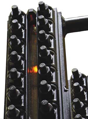
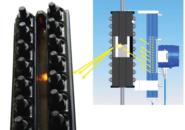
Recent developments in the level instrument industry have reduced maintenance for plant staff. The primary advancement has been with the development of LED illumination and viewing accessories for flat glass gauges (Figure 1) and ported-type water gauge glasses (Figure 2).
 |
| 1. Bright as day. LED illumination on flat glass gauge provides a brilliant, high-contrast image of the water level, visible day or night. LEDs typically provide 100,000-hour lamp life to reduce maintenance. Courtesy: Clark-Reliance Corp. |
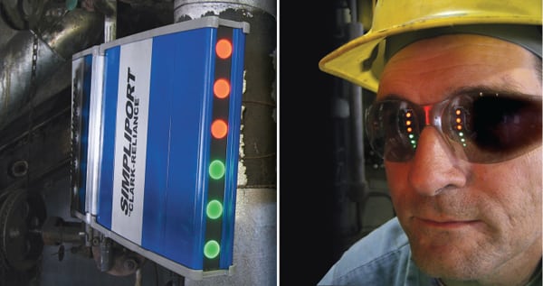 |
| 2. View at a distance. Ported type gauge glasses can be fitted with LED illuminators and viewing hoods to permit long-distance viewing of water level in high-pressure (up to 3,000 psi) applications. Courtesy: Clark-Reliance Corp. |
The work environment near boiler drums can be harsh. Traditional incandescent or halogen lighting required routine maintenance on potentially hot lighting fixtures. The marketplace now offers LED models that provide a bright image and consume a fraction of the power while greatly reducing the maintenance risks associated with their predecessors. Additionally, LED illumination requires little maintenance, and 10-year lamp life is very commonly available.
Other industry improvements contribute to increased water gauge glass service life, including high-quality original equipment manufacturer (OEM) components and well-documented instructions. The ready availability of OEM maintenance instructions on the web eliminates excuses for missed critical maintenance requirements.
Additional Rules for Remote Indicators
The rules in the Code are clear when it comes to remote indication for the control room. If the operator in the control area cannot see a gauge glass level there must be two independent (remote) indicators on continuous display for the operator. The logic behind this requirement is simple. If there are two completely independent indication systems that track with each other as the water level rises or falls, then the operator has confidence in the gauge glass level. If an operator has only one level indication, then how does the operator know that it is displaying properly?
Electronic displays have similar rules. If one of the displays is on a computer screen, it must be dedicated to this image or at least set up with the drum level similar to a “tool bar” so the screen can be manipulated without loss of display of the drum level information.
Given the importance of the measurement to staff and equipment safety, no compromise should be made when selecting boiler water level measurement equipment. The most common technologies used for remote indication of drum level include:
- Conductivity multi-probe systems that sense and remotely display the level with a panel indicator and also serve as a trusted technology for alarm and trip circuits. Differential pressure technology that relies on a pressure head and sensing lines near the drum to activate a remote display.
- Guided wave radar technology is the newest technology for these applications but also requires programming to ensure accurate level indication.
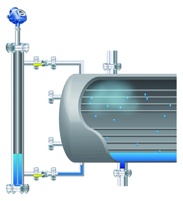
- Magnetic level gauges consisting of a stainless steel chamber with an internal float containing a magnet that attracts an externally mounted indicator. However, the Code limits use of these systems to 900 psi, due to risks for inaccuracy at higher and sliding operating pressures.
All of the above technologies have application in the boiler room but must be properly installed to prevent indication errors.
Recent Developments in Conductivity Probe Systems
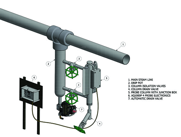
Conductivity probe systems, popular since the 1960s, have benefited from improvements in low-voltage technology. New systems have the intelligence to automatically monitor probe condition and to notify the control room that a blowdown of the probe column to remove residue and mineral buildup is necessary to maintain accuracy (Figure 3). These intelligent systems can reduce staff exposure to hazardous areas while extending probe and valve life. Additionally, system intelligence can identify probes that have become unstable and need to be replaced, further simplifying maintenance while improving system reliability.
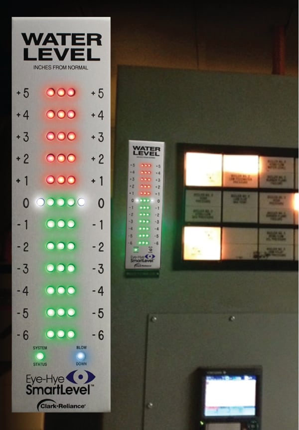 |
| 3. Remote maintenance. The modern control room display for a conductivity probe type system is shown. New “intelligent” systems automatically monitor probe conditions and instruct operators precisely when to blow down the column to clean the probes to maintain accuracy and reliability. Courtesy: Clark-Reliance Corp. |
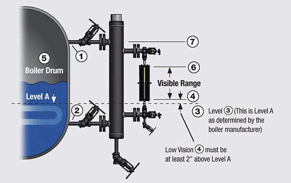
The placement of the indication range for any instrument must also meet strict requirements. The upper end of the range must not intersect the elevation of the lower outside edge of the steam pipe diameter exiting the drum. Also, the lower end of the indication range must not intersect the upper outer edge of the water connection pipe exiting the drum. Furthermore, the lowest edge of the indication range must be at least 2 inches above the lowest safe operating level that will not cause any harm to the drum internals.
The minimum pipe size requirement to feed instrumentation from the drum is 1 inch for water columns, standpipes, and low water cutout devices. The minimum drain pipe size is ¾ inch. However, the minimum drain pipe size for remote indication systems is ½ inch. Further, the minimum drain size from the lower valve associated with a water gauge glass can be 3/8 inch, as long as the inside diameter of the drain provides at least a ¼-inch diameter unrestricted bore. However, most installations use ½ inch as their smallest drain piping.
Valves Are Critical, Too
Mating piping and valves from the drum, field wiring, and system maintenance are also important parts of the boiler drum level sysem. The installation and type of isolation valves that are installed between the drum and level instrumentation are also critically important.
When isolation valves are installed between the water column and the drum (which is a Code option), they must be locked open. This action prevents actuation of these valves or false trips caused by unauthorized personnel isolating the actual water level from the instrumentation without operations staff knowledge.
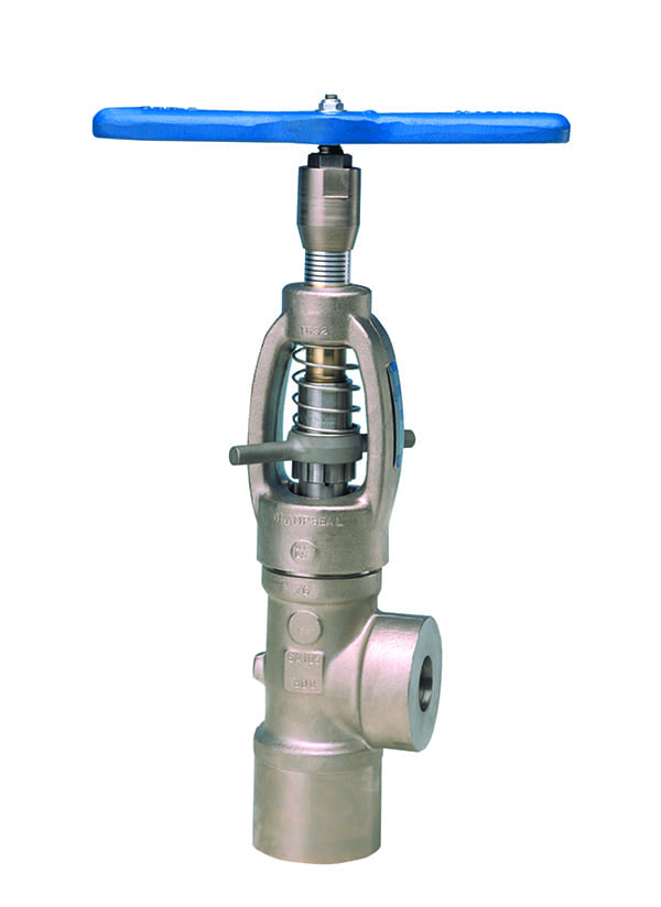
The types of isolation valves used include gate and globe types. Globe-type valves may provide longer service life in this application. However, the specific design requirements in Section 1 for globe-type valves for instrumentation mandate at least one-quarter of the inlet port diameter must be above the seat when the valve is open. This provides a straight line flow path within the valve and greatly reduces the risk of blockage caused by sediment buildup, which could result in a trapped level in the instrument. This important update to the Code (Section 1, Subsection PG-60) occurred in 2007.
The most common materials used for construction of the pressure components on level instrumentation are carbon steel pipe (SA106- Grade B), SA105 forged steel for valve bodies, SB-61 bronze for low-pressure water gauge valves (rated up to 450 psi), and various grades of stainless steel that are listed in the Code (Section 1, Subsection PG12). Other acceptable grades of carbon steel pipe and plate materials are identified in Section 2.
Proper Water Level Improves Heat Rate
While staff safety remains foremost, protection of the turbine and plant efficiency are also directly related to boiler drum water level. Properly maintained water level optimizes fuel efficiency. However, the added assurance against operating with a too-high water level may prevent saturation of internal drum steam separators and ultimately prevent water droplets (which carry particulate) from entering the steam outlet and the turbine.
There is much more to level indication instrumentation than meets the eye. The best place to learn more is by reviewing Section 7 of the Boiler Code or Recommendations for the Proper Care of Power Boilers. This section of the Code includes important information, such as:
- Boiler startup fundamentals
- Verification of water level in two or more devices
- Checking instrumentation and piping for leaks
If you have any doubts about the proper operation of the level instrumentation in your plant, consult with your safety department or your local jurisdictional inspection authority (state or insurance) to verify the requirements for your specific application. Finally, always follow the OEM guidelines for the installation and operation of level instruments to ensure that you have the most up-to-date and accurate information.
—Contributed by James W. Kolbus (jkolbus@clark-reliance.com), Clark-Reliance Corp.