Direct air capture (DAC) holds promise to extract carbon dioxide from the atmosphere, potentially becoming a crucial tool in the battle against climate change. Amidst heated debates over its feasibility, cost, and effectiveness, this comprehensive analysis dissects DAC’s potential through energy modeling and policy discussion. Can DAC truly fulfill its promise and play a significant role in achieving carbon neutrality—or will it fall short in the face of technical, political, and financial challenges?
In the contentious arena of climate policy, direct air capture (DAC) is an exceptionally controversial subject. DAC is one of a suite of methods for extracting carbon dioxide (CO2), the most common greenhouse gas (GHG), from the atmosphere. According to the Intergovernmental Panel on Climate Change (IPCC), carbon dioxide removal (CDR) will almost certainly be necessary to prevent the worst effects of climate change, and DAC is a primary option for implementing CDR. But in the eyes of some, DAC is nothing more than an expensive boondoggle and, worse, a backdoor for continued production and use of fossil fuels. Even among supporters, there is no consensus on which of the two primary DAC technology options is the best bet for implementation. And meanwhile, the climate clock is ticking.
This article will first review the case for CDR, then the technology options specific to DAC. The importance of CDR and DAC, in particular, is illustrated by examining the results of a recent energy modeling study, including the results from consulting firm OnLocation’s customized implementation of the National Energy Modeling System (NEMS). The merits of DAC versus other CDR approaches are also explored. The article concludes by contrasting the controversy over DAC with what the model results and policy studies suggest are the long-term need for the technology.
Why Carbon Dioxide Removal (CDR)?
The starting point is understanding the scale of the climate challenge that decision-makers are facing. The IPCC recently completed its sixth assessment cycle with a capstone report synthesizing the current scientific consensus on the climate outlook. The IPCC found that severe climate impacts are probable because the critical threshold—an increase in global temperatures of 1.5 degrees Celsius relative to pre-industrial levels—is likely to be breached:
“Only a small number of the most ambitious global modelled pathways limit global warming to 1.5°C (>50%) by 2100 without exceeding this level temporarily. Adverse impacts that occur during this period of overshoot and cause additional warming via feedback mechanisms, such as increased wildfires, mass mortality of trees, drying of peatlands, and permafrost thawing, weakening natural land carbon sinks and increasing releases of GHGs would make the return more challenging (medium confidence) [emphasis added].”
The consequences for the natural environment and the human population are potentially dire, including compound effects (overlapping droughts and heatwaves) that occur simultaneously across multiple regions, putting, for example, food supply at risk. In addition to the overarching need to reduce GHG emissions, a central problem is the “residual” emissions that are exceptionally hard and expensive to eliminate, including from aviation and agriculture. If it proves impossible to avoid atmospheric concentrations of CO2 and other greenhouse gases (such as methane) that result in warming above 1.5C, then the excess (overshoot) of GHG in the atmosphere and the continuing residual emissions must be corrected by removing CO2 from the air. In the view of the IPCC, because of overshoot and residual emissions, implementing CDR is probably not optional:
“Reaching net zero GHG emissions primarily requires deep reductions in CO2, methane, and other GHG emissions and implies net negative CO2 emissions. Carbon dioxide removal (CDR) will be necessary to achieve net negative CO2 emissions…. Achieving and sustaining net negative global CO2 emissions, with annual rates of CDR greater than residual CO2 emissions, would gradually reduce the warming level again (high confidence) [emphasis added].”
A Brief Overview of Existing DAC Technology
DAC, one of the primary options for implementing CDR, comes in two flavors: liquid absorption-based (L-DAC) and solid adsorbent-based (S-DAC).
At the most fundamental level, the methods are similar. Each uses a contactor containing capture media to extract CO2 from ambient air. Heat is then applied to release the CO2, which is compressed and transported by pipeline for commercial use (for example, enhanced oil recovery) or, for the most significant climate benefit, to a geologic repository for permanent storage. But beyond these basics, the technologies diverge greatly in terms of complexity, scalability, the factors that influence reliability, and thermal energy requirements.
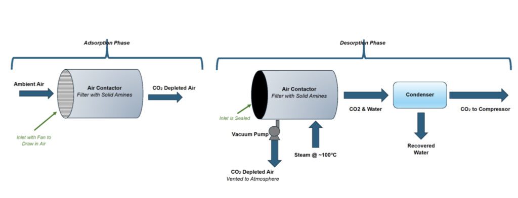
An S-DAC collection module is a single, comparatively simple unit that both traps and discharges CO2. As illustrated in Figure 1, fans draw ambient air through a filter impregnated with an adsorbent, such as solid amines. Once the filter is saturated with CO2, the contactor inlet is closed, and the air remaining in the contactor is pumped out and steamed to heat the filter to about 100C. In this process (called temperature-vacuum swing or TVS), the CO2 is released and swept by the steam out of the contactor into a condenser, where water is separated from the CO2 stream. The dry CO2 is directed to a compressor for transport to a repository, and the water is collected for reuse or other purposes. Because the amine filter captures water vapor as well as CO2 from ambient air, the system yields more water than is lost in the process, a plus for installations in arid areas.
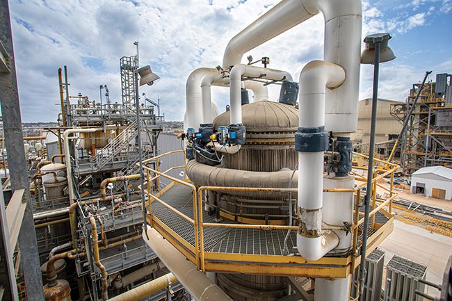
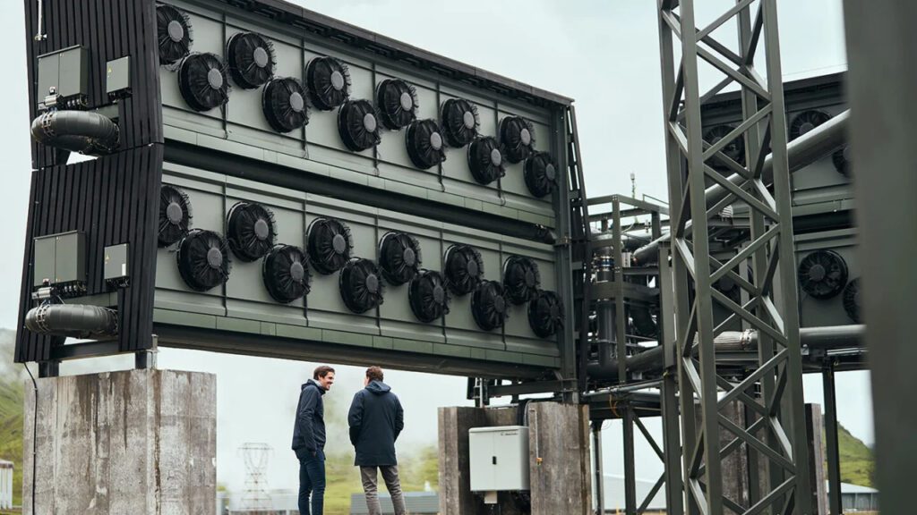
A single S-DAC module would capture about 50 to 100 tonnes of CO2 annually. A commercial facility would consist of multiple modules, with the option to increase capacity by adding more units over time. Figure 2 is an image of a pilot S-DAC plant, the Climeworks Argos facility in Iceland, designed to capture about 4,000 tonnes of CO2 per year.
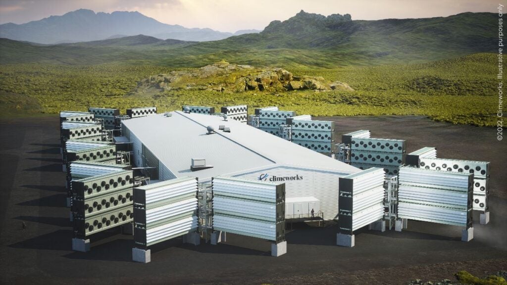
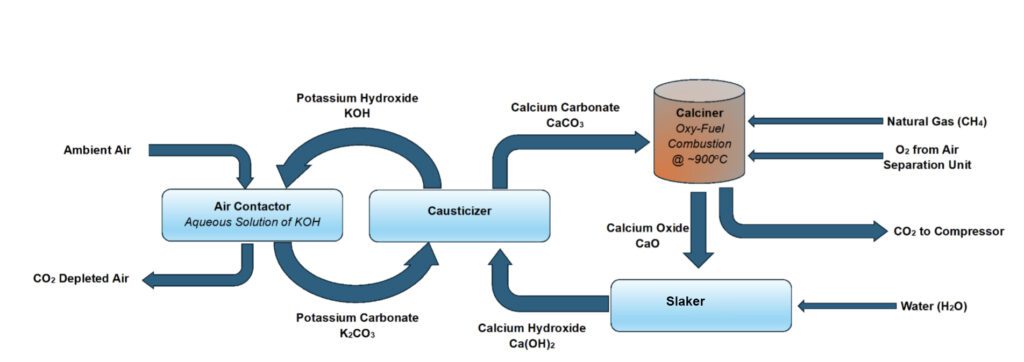
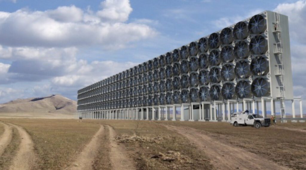
In contrast to the modular S-DAC approach, a commercial-scale L-DAC facility would consist of a large and complex integrated system. As illustrated in Figure 3, the contactor contains a solvent, such as potassium hydroxide (KOH), in an aqueous solution. Ambient air is blown through the solution, and the CO2 combines with the solvent to produce a water-soluble salt. In the next stage, the solution is treated with a flocculant, calcium hydroxide, to regenerate the solvent and produce pellets of calcium carbonate. The pellets are heated in a kiln at 900C to release a pure CO2 stream for compression and transport to a repository. The reject from the kiln is calcium oxide, which is treated with water to produce the calcium hydroxide flocculant. Figure 4 is a conceptual rendering of an L-DAC plant using technology developed by Canadian firm Carbon Engineering.
The L-DAC system has advantages over solid systems. Existing commercial technology uses liquid solvents to capture CO2 from a gas stream, albeit not for such a dilute concentration or such large volumes. S-DAC is a more novel and immature approach. A single large L-DAC plant may capture economies of scale unavailable to modular S-DAC facilities. And L-DAC technology operates as a continuous carbon removal process. This is in contrast to an S-DAC module, which operates in batch mode. A module stops collecting CO2 when the filter is saturated with CO2 and cannot resume capture until the TVS release cycle is completed. To achieve a target level of throughput, an S-DAC facility must pay for excess capacity (that is, extra modules) to compensate for the times when units are not operating in capture mode.
On the other hand, the S-DAC technology has, at least in principle, the benefit of simplicity. It does not depend on the smooth operation of a complex, integrated system, and the failure of a single module does not impact the remaining units. It is a net producer of water, whereas L-DAC is a net consumer. Another significant advantage is the low operating temperature (about 100C) of the TVS cycle. Steam at this temperature can be generated using waste heat from other facilities or produced from renewable sources. L-DAC requires temperatures in the kiln that are almost an order of magnitude higher. The heat can be produced by burning natural gas with pure oxygen (to maintain the purity of the CO2 stream released from the calcium carbonate and natural gas combustion), but this adds a novel oxyfuel kiln and an air separation unit to what is already a complex and costly technology.
More importantly, the carbon emissions associated with extracting, processing, transporting, and (in the absence of oxyfuel combustion) burning the natural gas will reduce the net carbon reduction from an L-DAC plant. Adoption of L-DAC technology may require developing a system that uses electricity from emission-free sources to provide the necessary thermal input.
Energy Modeling Forum Results and CDR Options
The potential importance of DAC to climate policy is illustrated by a recent Energy Modeling Forum (EMF)-sponsored study exploring how major North American economies—Canada, Mexico, and the U.S.—can achieve net zero carbon emissions. OnLocation participated in the study using the version of NEMS that it customized for the U.S. Department of Energy’s Office of Fossil Energy and Carbon Management (FECM). The FECM version of NEMS incorporates enhancements for analyzing climate policy scenarios, including DAC.
The EMF analysis included three primary types of CDR: land use, land-use change, and forestry (LULUCF), bioenergy with carbon capture and storage (BECCS), and DAC.
The first two options (LULUCF and BECCS) both use biological mechanisms to achieve negative emissions. LULUCF involves changing land use patterns, such as reforestation (planting trees in once-forested areas) and afforestation (creating forests where none previously existed). BECCS is more complex. It entails planting crops to extract CO2 from the atmosphere during the growing process and then using them as a biomass feedstock in a power plant or industrial facility equipped with a carbon capture, utilization, and storage (CCUS) system. The CCUS system removes and compresses the CO2 from the exhaust gas, which is then transported by pipeline to a site where it is injected underground for permanent storage. As discussed above, DAC dispenses with the biological component and is a purely technological solution.
The EMF study, which involved more than a dozen energy models running common scenarios (the results are summarized for the U.S. in a recent paper), examined a scenario in which net zero emissions are achieved by 2050. Every model projected a need for CDR to accomplish this goal (Figure 5).
The larger the residual emissions in 2050, the more CDR is needed to compensate. For example, for this study, FECM-NEMS did not include certain technologies, such as complete modeling of a hydrogen energy market. Consequently, FECM-NEMS projects a comparatively elevated level of residual emissions and a correspondingly greater need for CDR than many of the other models in the study.
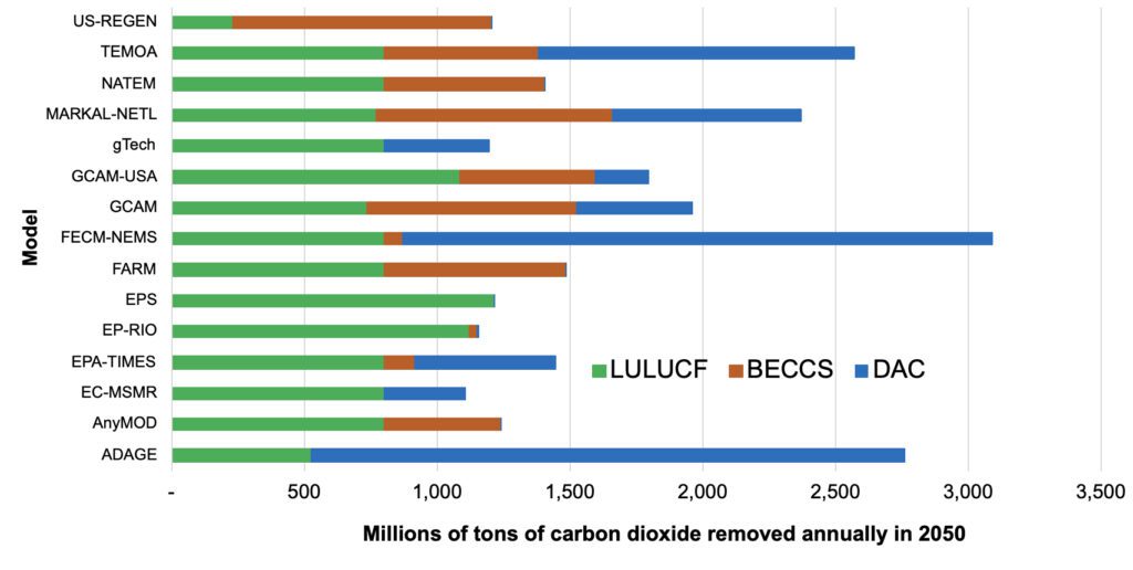
A commonality across most model results is reliance on LULUCF to achieve a base level of negative emissions of roughly 800 to 1,000 million metric tons (Mt) of CO2 capture (this reflects either a model result or an exogenous assumption). From this base, the models diverge in their selection of CDR methods. In particular, FECM-NEMS is one of two models that rely heavily on DAC.
This is arguably counter-intuitive: DAC is a controversial, costly, and largely unproven technology. But as discussed below, it has advantages over other options, which may make it a primary choice for negative emissions.
DAC’s Advantages Over Other Options
LULUCF is probably the most elegant and inexpensive approach to negative emissions. BECCS has a comparable biological component and uses CCUS technology that, if not yet fully proven, has a much longer track record than DAC. But biological options have limits and risks.
Dedicating land to biomass crops or trees can reduce the acreage available for growing food. Switching from traditional to biomass crops can disrupt local communities, especially disadvantaged and Indigenous populations that are already disproportionately feeling the impacts of climate change. Forests and biomass crops are also vulnerable to wildfires. This threat will grow as the earth warms and social and economic needs change, which might drive communities to repurpose biological sequestration sites, releasing the stored carbon. BECCS also has the disadvantage of being tied to carbon capture at the point source—the power plant or industrial facility—where the biomass is burned and the CO2 released.
This means that extensive use of BECCS will need to be accompanied by the creation of an equally extensive network of pipelines to move compressed CO2 to geologic locations where it can be safely and permanently sequestered. The construction of a massive pipeline network would be costly and likely face intense public opposition due to safety and environmental concerns.
DAC does not have the disadvantages of the biological options. DAC facilities use much less land than LULUCF or BECCS to capture an equal volume of CO2, even accounting for the wind or solar farms needed to supply electricity. Scale-up and deployment are not limited by the acreage available for planting, and because DAC facilities are not tied to point sources, they can be placed anywhere, including land not useful for other purposes. An attractive option is to locate DAC facilities near geological repositories, reducing the need to create a pipeline network to transport CO2. Finally, the volume of CO2 injected into an underground repository can be measured and verified with a precision that is not possible with LULUCF.
Congress and the Biden administration have recognized the potential benefits of DAC. The Bipartisan Infrastructure Act provides $3.7 billion in funding to promote CDR, including the creation of four DAC hubs where facilities and supporting infrastructure can be concentrated to yield economies of scale. In August 2023, the Department of Energy (DOE) announced the award of $1.2 billion to build two DAC facilities, each with the capacity to extract 1 million metric tons of CO2 annually, located in Louisiana (Project Cypress) and Texas (the South Texas DAC Hub). These plants will extract 250 times more CO2 than the largest existing DAC plant. DOE is also funding design studies for another 19 projects at an earlier stage of development.
The Controversy and the Value of Models
DAC, however, is a controversial technology, including within the environmental community. One point of contention is the expense. It currently costs a DAC plant on the order of hundreds of dollars to more than $1,000 to capture a ton of CO2. DOE’s objective—the “Carbon Negative Shot”—is to reduce this to under $100 per ton of CO2 by 2050, but it has a long way to go. Technical feasibility is also a question. There are currently about 18 DAC plants operating worldwide that, combined, remove about 10,000 tons of CO2 annually. The world’s largest facility, the Orca plant in Iceland, captures only 4,000 tons of CO2 annually. DOE estimates that by 2050, CDR will have to be operating at the scale of billions of tons (gigatons) of CO2 capture. To achieve this, the technology will have to be successfully scaled up by orders of magnitude. DOE frankly states that perfecting and deploying CDR is “one of the toughest remaining barriers to achieving net-zero.”
However, the central dispute is whether DAC is a solution, distraction, or, even worse, a trojan horse that will delay reducing fossil emissions. The distraction argument contends the absolute priority must be to reduce GHG emissions by adopting renewable energy, energy efficiency, electrification, and behavioral changes. According to this viewpoint, DAC and other negative emission initiatives simply divert attention and resources from this primary goal. DAC is especially problematic because to be a trustworthy source of negative emissions, a DAC facility must be powered by natural gas with additional CO2 capture or renewable electricity, and the build-out of solar and wind power, and the transmission lines needed to move the power around, is just beginning.
The trojan horse concern, meanwhile, suggests that the fossil fuel industry and some policymakers will treat DAC as a “get-out-of-jail-free card,” arguing that fossil fuel production and combustion can continue indefinitely at high levels because DAC provides a means to trap the offensive emissions before they can do any harm.
These arguments against deploying DAC (or other versions of net negative emissions) amount to a Catch-22. On the one hand, it is true that with an immediate, massive, global effort to reduce emissions and deploy renewables, it might still be possible to rapidly achieve net zero and stay within the 1.5C threshold. But on the other hand, if the gamble on this unprecedented level of global cooperation and investment falls short, then CDR will absolutely be needed to prevent the worst climate impacts.
In this case, the sooner work begins on perfecting DAC and other CDR methods, and the sooner carbon extraction and sequestration begin, the better. As illustrated in this article, models of the energy transition, such as OnLocation’s implementation of NEMS, may help decision-makers evaluate these kinds of climate policy dilemmas and offer insights into pressing questions: What are the optimum and feasible approaches to reducing emissions? How do we plan now for future climate contingencies, and what mix of policy and incentives will spur the necessary investments and changes in individual and business behavior?
—Stan Kaplan (Stan.Kaplan@Keylogic.com) has worked in the electricity and fuels areas since 1978, as a consultant, regulator, utility executive, and until retiring in 2018, a senior manager with the Department of Energy. He is currently an energy consultant with KeyLogic.
Corrected (March 10, 2024): Clarifies L-DAC process and makes an important correction to Figure 3.