When a gas turbine goes down, recovery can be an expensive, time-consuming process. Knowing what can go wrong and how to anticipate turbine failures can help you avoid a difficult unplanned outage.
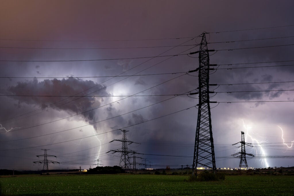
Gas-fired power is hot and getting hotter. The Energy Information Administration estimates that 2016 will be the first year ever that the U.S. generates more electricity from gas than coal. New combined cycle plants, many of them over 1,000 MW in capacity, are starting up almost every month, and as coal plants continue to close across the nation, many workers who spent much of their careers in coal are moving or being transitioned by their employers to gas-fired plants (see “Balancing Risk, Reliability, and Safety at Plants Slated for Retirement” in the April 2015 issue).
In this environment, the number of power sector workers new to gas turbines is growing, and a review of what can go wrong with this equipment is useful. Though both steam turbines and gas turbines are types of rotating machinery, their failure modes of are not the same (this might seem obvious, but it bears repeating anyway). Even experienced workers can benefit from a refresher. This article is not intended as a comprehensive overview—books have been written on the subject—but as a starting point for further discussion and study. Note that while aeroderivative and industrial combustion turbines each have unique challenges keeping their gas path clean, all combustion turbines have a common set of operational challenges.
Recoverable Losses
Whatever contaminants exist in ambient air will wind up inside the turbine unless they are filtered out. These can include dust, sand, moisture, oils, and anything else that can be suspended, even temporarily, in air. This also includes anything dissolved in water that enters the turbine (such as via inlet fogging), as the heat of compression will separate dissolved materials from the water.
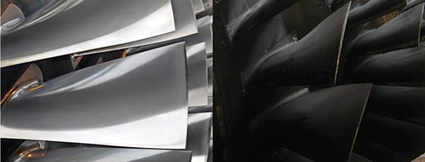
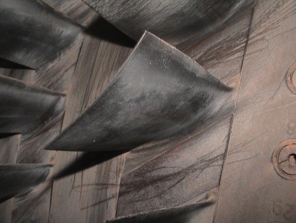
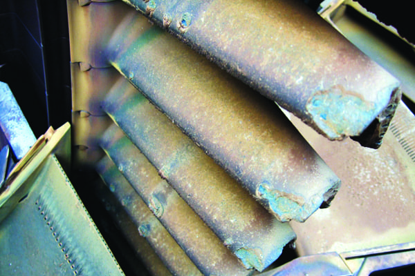
Turbine compressors are very effective filters, and foreign materials entering them often build up on blades and other surfaces. Salts will bind to metals and cause corrosion. Oils and waxes will themselves collect other contaminants and bind them to compressor surfaces. Collectively referred to as fouling, these effects roughen blade surfaces and change blade profiles and compressor airflow, reducing power and efficiency, clogging tight clearances, and increasing fuel consumption (Figure 1).
 |
|
1. Gradual deposits. Fouling and other deposits can occur on both compressor blades and those in the turbine section. Courtesy: Seoul National University |
The importance of proper air filtration has been known for many years, but continual improvements in filter media have shown that the advantages of using high-efficiency filters generally outweigh negative effects from increased pressure drop. Even small amounts of particles under 1 μm will result in fouling over time (see “Options for Optimizing Combined Cycle Plants” in the December 2015 issue).
On- and offline washing are common procedures used to reduce fouling on compressor blade surfaces in order to recover lost performance and efficiency. Another approach is the use of an abrasive cleaner such as rice or walnut shells injected into the compressor at low speed. Used properly, these materials will remove deposits without damaging the blades.
Foreign materials that pass the compressor and enter the turbine form hot deposits that cannot be removed through washing. These require an overhaul to recover lost performance.
Non-Recoverable Losses
Other types of lost performance cannot be recovered except through repair or replacement of the affected components.
Erosion and Abrasion. Some materials that enter the compressor, rather than binding to surfaces, can erode them away. As these are typically larger particles, standard filter media are usually able to remove them from inlet air, though even particles down to 10 μm can cause erosion. It needs to be remembered, however, than anything injected into the air stream, such as water used for inlet NOx control, cooling, or washing, can cause erosion. Erosion can occur on both leading and trailing edges of the airfoil. Like fouling, erosion causes changes in blade profiles, airflow, and clearances.
Abrasion is a similar process to erosion, caused by moving surfaces rubbing against stationary ones. A new, properly tuned turbine should not suffer from abrasion; it usually occurs as a result of other types of degradation. As clearances change and alignments shift over time, vibration can increase and changes in orbital amplitude can bring rotating elements into contact with other surfaces.
The causes of abrasion are many. Improper maintenance and tuning, fouling, excessive wear in bearings and seals, thermal creep, misalignment in components and couplings, and many other problems can all cause rotating elements of the turbine to come into contact with stationary surfaces. Further, these problems will build on one another, as abrasion can throw the rotor out of alignment, which increases vibration, which places greater stress on bearings and seals, causing greater misalignment and more abrasion, and so on.
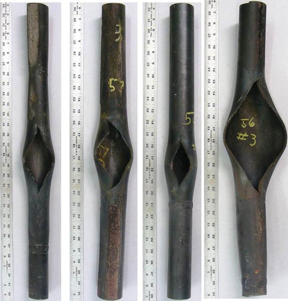
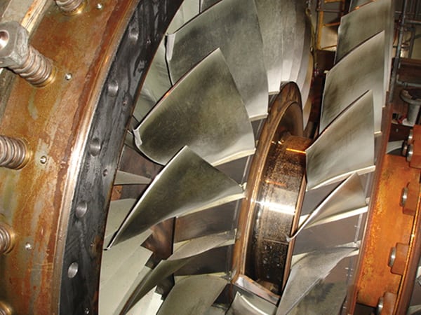
Foreign Object Damage. This is essentially a more serious version of erosion. Though far more common with turbines used on aircraft (which have open inlets), industrial combustion turbines can also sustain severe damage from objects entering the compressor. Unlike aircraft engines, this damage occurs almost entirely as a result of tools and other debris left inside the air inlet during maintenance or components that break free from their mountings. Malfunctions in auxiliary systems such as the water wash can also result in blade damage if they cause solid materials to enter the compressor (Figure 2). One thing to keep in mind is that such debris need not be especially large. Turbines have been gradually destroyed by small pieces of components—such as inlet screens—corroding and breaking apart over time. Proper maintenance procedures are usually sufficient to prevent this sort of damage, but when it happens, the results can be catastrophic.
 |
|
2. Ice attack. The blades in this turbine compressor were damaged when water from a leaky wash system froze in cold weather and the ice broke free and entered the turbine. Source: POWER |
Corrosion. Anything that enters a turbine, including fuel and ambient air, has the potential to react with metal components. Many types of chemical reactions are possible, and these can lead to many different types of corrosion. The effects of corrosion can resemble both fouling and erosion. Some types of corrosion cause a buildup of corrosion products, while others cause metal to be stripped away.
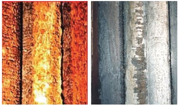
Oxidation is a chemical reaction between oxygen and metal components. Oxidation rates increase with temperature, which means it is of primary concern in areas of high temperature, such as the combustor or hot sections of blades. Hot corrosion is a specific type of oxidation that occurs at high temperatures (>550C) between metal components and salts deposited on them (Figure 3). It is of particular concern for gas turbines because it causes cracking in areas under extreme stress, such as the bases of turbine blades. For this reason, maintaining purity of both fuel and water used for injection is of critical importance. Contaminants such as sodium and potassium chloride, sulfur, vanadium, and lead (the latter two often used as additives in liquid fuels), can all cause hot corrosion.
 |
|
3. Hot take. Hot corrosion results from contamination of the turbine blades with salts and other substances while at high operating temperatures. Courtesy: Sulzer |
Pitting is another form of corrosion that results in localized formation of holes in metal surfaces. Pitting occurs when conductive impurities, such as water, come in contact with microscopic cracks. Over time, the crack widens into a pit, which can then lead to much larger cracks. The same process can occur in crevices between turbine components. Pitting is most often a problem in the compressor, where the blades come into contact with inlet air impurities. Frequent cycling is also a source of pitting, as water can condense on compressor blades after the turbine is shut down.
Fatigue. The extreme temperatures that turbine blades are subjected to can eventually result in thermal fatigue. This can be caused or aggravated by many factors: frequent cycling; deposits and corrosion that interfere with heat transfer; combustion and airflow problems that cause temperature differentials; excessive vibration; failure to follow manufacturer recommendations for controlling thermal stress during startup and shutdown; as well as others. Fatigue results in microscopic cracks that can serve as sites for corrosion as well as growing into large cracks that result in blade failure.
A more in-depth discussion of degradation modes can be found in “Gas Turbine Degradation,” a presentation given at the 2014 Texas A&M Turbomachinery and Pump Symposia, from which some of the above is adapted.
Keeping It Clean
The impacts mentioned above can be limited through the use of anti-corrosion and anti-fouling coatings and first-stage blades designed for enhanced durability, but scrupulously maintaining unit cleanliness over the long haul is the best approach to prevention. Though some contaminants can be removed with water washing, many cannot, and the washing process itself can cause additional fouling, erosion, and corrosion if not conducted properly. For these and other reasons, the use of demineralized or better quality water is recommended for any water that enters the turbine. The use of city water or surface water, even temporarily, will eventually result in problems.
Much the same concerns apply to fuel supply. Liquid fuels, because of impurities and additives, are typically a greater risk than natural gas, but impurities in gas are also capable of causing significant erosion and corrosion. Gary Stansbury, general manager of gas turbine services for MD&A, told POWER in an August interview that one of the biggest sources of problems he sees is dirty gas. “If dirt and contaminants can get past the strainers and into the combustor, that will cause a big issue with the combustion process in the unit.”
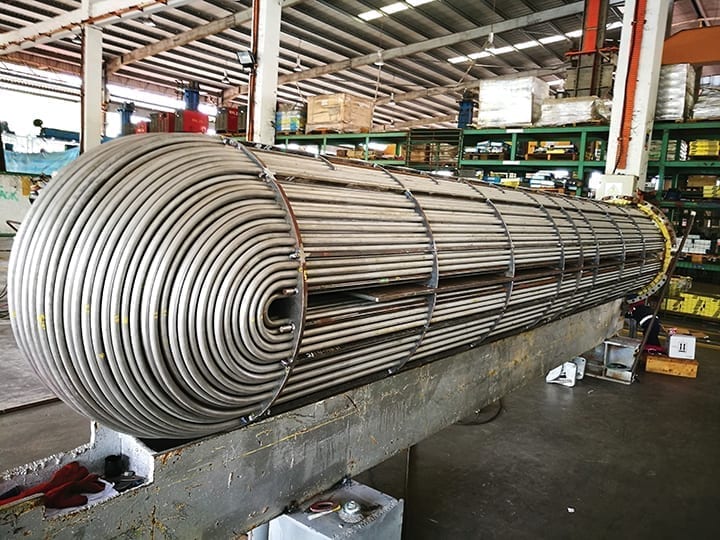
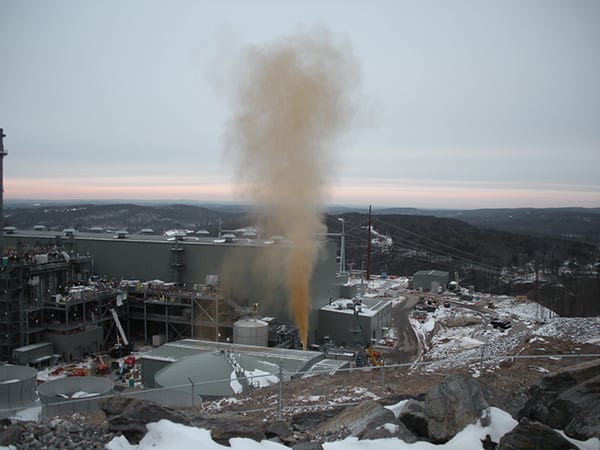
Such contaminants in the gas supply can come from both the pipeline supplying the plant and the plant fuel supply system, if the latter was not properly blown out during construction or at any time it was opened since then (Figure 4). In addition to cleanliness issues, dirty gas can change combustion dynamics and cause increased stress on the turbine, such as elevated exhaust temperatures. Stansbury told POWER about a client he worked with that was experiencing repeated trips as a result of turbine exhaust temperatures. The problem was eventually traced to a petroleum-based product in the gas that the filters were not properly configured to remove.
 |
|
4. Clean blow. Gas supply lines are blown out before operation to remove rust, corrosion, and other debris. Imagine if the contaminants in this debris cloud had instead found their way into a turbine. Courtesy: Chemical Safety Board |
Dual-fuel units, particularly those that operate on fuel oil only as a backup, require special considerations, Stansbury noted. Liquid fuel supply systems that sit unused for months can degrade to the point that they may not be available on short notice, such as if the plant has committed to run during a period when gas is suddenly not available. “These operators need to understand that you should run your liquid fuel system periodically just to make sure all of those components are working properly,” he said.
For more on these issues, see “Best Practices for Natural Gas Line Cleaning” in the September 2011 issue, “The End of the Line for Pipe Cleaning with Natural Gas?” in the February 2012 issue, and “Real-Time Monitoring of Natural Gas Fuel Cleanliness” in the June 2010 issue.
Design and Manufacturing Problems
The design and engineering of gas turbines, like nearly all technologies, has continued to evolve. While this means that current state-of-the-art designs are engineered to limit known failure modes to the greatest extent possible, it also means that older turbines and previous designs do not have the preventative elements of modern ones. Upgrades exist for many issues, but not all older turbines have been upgraded, or upgraded properly, for a variety of reasons.
Ian Summerside, global product line manager for Ansaldo Energia subsidiary PSM—one of many companies offering aftermarket upgrades—told POWER in an August interview that they continue to see the results of design oversights in the field.
Summerside also noted that many turbines are being used for different roles than they were originally designed for or are being called upon to run longer periods or cycle more often. Older units are often upgraded to increase their output, which places greater stress on components designed for lower power.
“If you are taking an older turbine and you are trying to get more power out of it or increase your efficiency, you might be relying on a component that is 15 years old, and that may have had an inherent flaw in it that hasn’t been a problem up to now, but that can become an issue after these upgrades,” he said.
Manufacturing and quality control have improved considerably in the past few decades, which also means older units were not manufactured to the same standards as newer ones. Additionally, Summerside noted, older units may have been serviced and modified by several different companies, not all of which perform work to the highest standards. Attempts to save money on upgrades in past years can come back to haunt current staff.
One of the most common ways these problems can crop up, Summerside said, is in thermal creep of turbine blades, especially in areas that operate at the greatest temperatures. “Even with all the cooling air and protective design elements, the first-stage blades in the turbine section are operating at such high temperatures that the metal can almost be like rubber at the end of the blade. It is very soft and has lost much of its structural rigidity.” Over time, the blade can deform, stretch out, and start to rub. Gas turbines are designed to account for this problem, but when operating profiles change, that can take the turbine outside of its design envelope and cause damage.
Another area where older turbines may suffer is with design oversights that can increase fouling. Many older designs, Summerside said, can experience foreign material buildup in the blade cooling system. Because turbine blades are designed to experience a certain amount of movement in the attachment to the rotor, any changes in expected movement can change behavior of the blades during operation, sometimes with catastrophic consequences. Such buildup in the cooling system, over time, can restrict movement of the blades, ultimately locking the blade in place if it gets severe enough. In some cases, Summerside said, this can change resonance of the blades enough to cause them to liberate, a failure that usually results in severe-to-fatal damage to the rest of the engine. Proper filtration of cooling air can reduce the problem. Modern designs include a dirt trap that will prevent buildup in critical areas, but it must be cleaned out periodically.
As turbine designs change to meet new market demands, they can change maintenance practices in ways older staff may not fully understand. Stansbury noted that some operators can be unclear on how to properly calculate maintenance intervals according to original equipment manufacturer (OEM) recommendations, especially on units that have changed their operational profiles or that cycle frequently. “A lot of customers take it for granted that it’s easy to understand how to schedule a particular outage.” In fact, it can be deceptively complicated, he said. “They think it is either hours or starts, but they need to understand the impact of different modes of operation on those maintenance intervals. For example, if they’ve got a peak firing mode, or a fast-start capability, there are other factors that go into OEM recommendations.” Not all starts and operating hours are created equal.
Murphy’s Law
Finally, operators need to be mindful that not all goes according to plan, and mistakes—some glaring—get made, whether during design, manufacturing, construction, operation, maintenance, or upgrades. Summerside told POWER the story of one particularly frustrating episode. A client plant with three identical units began experiencing severe emissions excursions with one turbine. While the others worked fine, the third simply could not be tuned to keep CO emissions within limits during low load. The problem was severe enough that the plant could not run that unit during low-load operation. Repeated testing did not reveal the problem, nor was PSM able to find the issue, even though the three units were supposedly identical. The problem persisted for three years of operations until PSM was called back to overhaul the combustion systems.
When the combustors were disassembled for service, the problem was finally uncovered: On one of the air manifolds supplying one of the combustion cans, a flange on the pipe was covered with duct tape. The tape had been placed there during a previous outage to prevent debris from entering the manifold, but it was not removed when the system was put back together. Though somewhat degraded from years of operation, the duct tape—the staple of so many repairs by craftsman amateur and professional—had survived to interfere with airflow in the combustor until it was discovered.
The moral, Summerside said, is that proper maintenance checks and documentation matter now as much as they ever did. ■
—Thomas W. Overton, JD is a POWER associate editor.