Innovative welding techniques can produce consistently better-quality joints. Special alloys, appropriate pre- and post-weld heat treatment, and proper weld procedures can all help prevent catastrophic failure of safety-critical systems.
The planned surge in new electricity power generation plants and retrofits across the world over the next two decades will provide outstanding opportunities for the fabrication sector. Recent innovative developments in welding equipment will support the drive toward the production of consistently better-quality joints, many of which are in the safety-critical class.
According to the World Nuclear Association, 335 nuclear reactors have been proposed throughout the world as of August 2018, of which 136 are in China, 28 in the U.S., and 22 in Russia. India’s massively delayed nuclear power program is expected to see a resurrection after Électricité de France (EDF), the world’s largest electricity company, agreed to build six nuclear reactors in the country; 22 other reactors have also been proposed. The Indian Jaitapur project is expected to become the world’s biggest nuclear contract and one of the world’s largest nuclear sites—nearly 10 GW.
Fossil fuel-powered generators are also expected to play a major part in the ever-increasing global demand for electricity. An estimated 1,000 GW of new coal-fired power stations will be built in the next 20 years, according to the International Energy Agency. Half of those will be in China, but there are also significant new-build programs in South Africa and India. Most of the existing global coal-fired installations are old, and maintenance programs will need to be implemented, potentially coupled with the introduction of carbon capture and storage retrofits.
All the programs involve extensive fabrication of steel pipes and tubes, the welding of which presents particular challenges.
Material Requirements
Stainless steels are used extensively in the construction of nuclear power plants, primarily for their corrosion resistance. Core and secondary parts of most reactor types in service today, including pressurized water reactors, boiling water reactors, advanced gas-cooled reactors, and fast breeder reactors, are built from stainless steel, as are reprocessing plants and research reactors. The nuclear decommissioning and waste storage industry is also a prime user of high-quality stainless for different types of transport or storage canisters and boxes for low- to high-level waste.
The high pressures and temperatures used in steam generation circuits necessitate the use of creep-resistant steels, such as those based on chromium/molybdenum/vanadium alloys. These materials provide improved oxidation and corrosion resistance together with high strength and are widely used in both fossil fuel and nuclear power plants.
The demand for quality in all these safety-critical joints is reflected in the stringent regulations laid down in welding procedures. Nevertheless, some welding practices can result in significant reductions in both corrosion resistance and mechanical strength.
Welding of High-Pressure Steam Pipes and Stainless Steels
Some engineering alloys are prone to cracking during welding. Industry sectors having to overcome this problem are principally in the power generation sector. The materials include low- and medium-alloy steels that have been specially developed for their high strength. Metallurgists have learned that heating joints prior to and after welding (pre-heating and post-heating) can reduce the sensitivity to cracking quite significantly. These processes involve temperatures of about 200C (392F), although much higher temperatures may be required for certain materials.
An example of a commonly used alloy benefitting from this treatment is SA213 T91 or SA335 P91. This is a ferritic alloy steel that meets the condition of creep resistance required in high-temperature steam generating plants. The material—often simply referred to as P91—has been in successful use for the last two decades in power plant service.
Pipe welding is one process that is widely used during manufacture. This affects the microstructure. Preheating, maintaining inter-pass temperatures, and post-weld heat treatment procedures are very critical for P91 and similar alloys. Failure to follow the procedures can result in catastrophic failures in service. Other high-temperature, creep-resistant ferrous alloys requiring this type of heat treatment include ASTM A389 Grade C24, A356 Grade 9, DIN 21CrMoV5-11, 15CrMoV5-10, GS-17CrMoV511, EN G17CrMoV5-10, and GE B50A224.
The preferred welding procedures in this type of fabrication are gas tungsten arc welding (GTAW) and gas metal arc welding (GMAW), which offer protection of the exposed upper-fusion zone. The joint around the underbead, however, needs to be protected simultaneously by purging the air that could be in contact with this underbead, known as the root weld, thus protecting the exposed metal by using an inert-gas envelope.
Meeting the requirements of inert-gas purging when temperatures exceeding 200C are involved necessitates the use of purge systems capable of withstanding these temperatures throughout the heating and welding cycles. Typical thermal cycles can exceed two hours, and it may be necessary to maintain the purge system in place throughout.
Specially engineered purge products have been designed over the past five years that are capable of withstanding the temperatures involved while at the same time maintaining excellent gas-sealing characteristics. They are also rugged enough to survive multiple-use applications. Weld-purging systems are available that can be used at the high temperatures prevailing during pre- and post-heating.
One area of production that regularly receives little attention is during pipe and tube fabrication where welding is widely used. Unless strict welding schedules are adhered to, however, not only will discoloration (heat tint) take place, but also corrosion resistance can be significantly reduced.
Mechanisms of Corrosion
Stainless steels owe their resistance to corrosion to the formation of a very thin (5–10 millimeter [mm]), transparent surface layer of chromium oxide. This provides a passive film that acts as a barrier to penetration by an invasive environment. When heated to a high temperature in the presence of oxygen, this film increases in thickness until it becomes visible—the color becomes darker with increasing film thickness.
At a critical film thickness, the film becomes unstable and begins to break down. The fractured zones created offer sites for localized corrosion. Four principle mechanisms are involved: crevice corrosion, pitting corrosion, stress-corrosion cracking, and microbiologically induced corrosion (MIC).
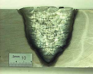
Crevice Corrosion. Localized corrosion of a metal surface can be attributable to the proximity of another metal such as a weld (Figure 1). It is a locally accelerated type of corrosion and is one of the major corrosion hazards in stainless steels.
 |
| 1. Localized corrosion. This image shows crevice corrosion adjacent to a stainless-steel pipe weld. Courtesy: Huntingdon Fusion Techniques HFT |
Pitting Corrosion. This produces attacks in the form of spots or pits (Figure 2), and takes place at points where the passive layer might be weakened. It occurs in stainless steels where oxidation has reduced the passivity. Once the attack has started, the material can be completely penetrated within a short time.
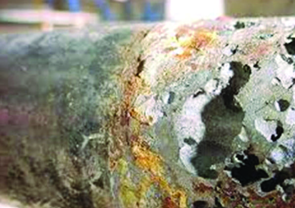 |
| 2. This is the pits. This image shows extensive penetration following pitting corrosion in a stainless-steel pipe. Courtesy: Huntingdon Fusion Techniques HFT |
Stress Corrosion Cracking. This is characterized by cracks propagating either through or along grain boundaries. It results from the combined action of tensile stresses in the material and the presence of a corrosive medium. It can be induced in some stainless steels by adverse heat treatments such as those occurring in weld heat-affected zones.
Microbiologically Induced Corrosion. Corrosion promoted or caused by microorganisms—usually referred to by the acronym “MIC”—is common in welded sections.
To avoid these forms of corrosion it is essential that heat tints are properly removed before the stainless-steel equipment or piping is exposed to aggressive or aqueous environments. The alternative is to prevent heat tinting during the welding process by using an inert environment to protect the surface (Figure 3).
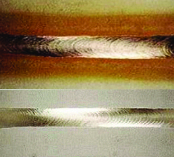 |
| 3. Oxygen content affects results. Even very-low-oxygen content in protective gases can cause discoloration in stainless steel. The image on top shows a weld produced using inert gas containing only 60 parts per million (ppm) of oxygen (0.006%), while the image on the bottom shows a weld produced with a protective gas oxygen content of 20 ppm (0.002%). Courtesy: Huntingdon Fusion Techniques HFT |
Removal of Heat Tint
Bright annealing or acid pickling can remove light discoloration, but heavier deposits may require machining such as grinding and polishing. Removal clearly requires access to the area in question, not only for treatment, but also for debris removal. Even when access is available, none of these treatments is easy and most can be very expensive.
While it is not too difficult to protect the outside surface of a weld by using an inert gas as coverage, preventing oxidation and loss of corrosion resistance on the inside is often overlooked. The technique of inside protection is known as “weld purging” and uses inert gas to flush out air, and thus oxygen, before, during, and after welding while waiting for the joint to cool below its oxidation temperature.
Weld Purging Techniques
Equipment has been developed over the past decade to make purging much easier. Currently available systems are robust and suitable for multi-use applications. They can be supplied to cover the size range between six and 88 inches (152 to 2,235 mm).
These are programmed to control gas flow and pressure during inflation and purging, and once placed in position, require little more input from an operator. The dams are fabricated using advanced engineering polymers and are thus suitable for use with oil and gas pipelines, and processing plants where elimination of contamination is essential.
Purge gas oxygen content can be controlled by using special oxygen-monitoring instruments called Weld Purge Monitors. These instruments not only measure oxygen levels but will also inhibit welding if the level is above a setpoint predetermined by the operator. Recording and analyzing software provides information for quality-control purposes.
Even very low oxygen concentrations in weld gases can give rise to discoloration, loss of corrosion resistance, and reduction in mechanical strength. Controlling the oxygen level in purge gases can be affected simply and efficiently using contemporary integrated purge systems. ■
—Michael Fletcher, PhD is the senior research and development consultant for Huntingdon Fusion Techniques HFT (www.huntingdonfusion.com).